Derale Performance 16 Pass Electra-Cool Remote Transmission Cooler Kit, -6AN Inlets User Manual
Diagram #1, Diagram #2, Diagram #3
13900-InstructionSheet
Derale Performance, Los Angeles, CA
800.421.6288 www.derale.com
INSTALLATION INSTRUCTIONS
ELECTRA-COOL TRANSMISSION COOLER KIT
PART # 13900
KIT CONTENTS
QTY. DESCRIPTION
1
Oil Cooler Assembly
1
-6AN Male x 3/8” Barb Fitting
3
-6AN Female x 3/8” Barb Fitting
10ft OEM Spec Hose
2
3/8” Compression Fitting
2
5/16” Compression Fitting
2
3/8” NPT Female x
3/8” Barb Fitting
1
Thermostat Switch
QTY. DESCRIPTION
1
In-line Thermostat Fitting
4
Hose Clamp
4
1/4”-20 x 1” Hex Bolt
8
1/4” Washer
4
1/4”-20 Lock Nut
4
6” Zip Ties
1
#10 Blue Ring Terminal
2
Blue Female Connector
1
Blue Wire Tap Connector
COOLER LOCATION
COOLER INSTALLATION
The purpose of a remote mount cooler is to be able to mount the
cooler away from the front of the vehicle therefore not blocking
airflow to the radiator/condenser.
This cooler can be mounted anywhere space permits. Always
keep in mind that the cooler still needs access to airflow to
perform at its peak.
1. Hold the Oil Cooler Assembly in the desired location.
2. Using a marker, mark the four hole locations.
3. Using a drill and 9/32” drill bit, drill the four mounting
holes.
4. Identify the 1/4”-20 x 1” Bolts, 1/4” Washers & 1/4” Lock
Nuts supplied and attach the Oil Cooler Assembly.
(Continues on Page 2)
Please read these instructions completely before starting the installation.
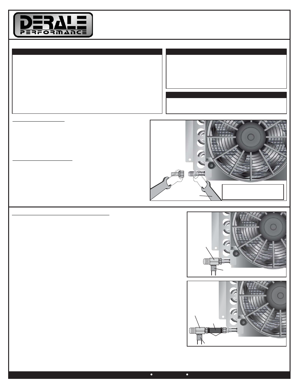
Always use backup wrenches when tightening fittings.
The AN fittings supplied in this kit do not require any
thread sealant. (See Diagram #1)
IMPORTANT
IN-LINE THERMOSTAT INSTALLATION
Mounting Location
There are two options for installing the In-Line Thermostat.
1. Cooler inlet installation
2. Hose installation
The recommended location for the In-line Thermostat Fitting is on the INLET side
of the oil cooler, so the oil line that provides the cooler fluid from the transmission.
Always use two wrenches when tightening the In-line Thermostat Fitting to
the oil cooler; failure to use a back up wrench could cause damage to the cooler core.
The In-line Thermostat Fitting is provided with a -6AN male and female threads.
a) Attach the In-line Thermostat Fitting onto the INLET fitting on the oil cooler.
b) Using Loctite or suitable sealant, carefully HAND TIGHTEN
the
Thermostat Switch clockwise onto the In-line Thermostat
.
Do not use a wrench or damage to the Thermostat Switch could occur.
The kit provides two brass fittings that are only used with this option. They are
designed to adapt the AN fittings to hose barbs.
a) Using the -6AN Male x 3/8” Barb Fitting provided, attach the fitting
to the female side of the In-line Thermostat Fitting.
b) Using the -6AN Female x 3/8” Hose Barb Fitting provided, attach the
fitting to the inlet on the cooler.
c) Using the OEM Spec Hose and Hose Clamps provided, cut the hose to
the desired length and attach one end of the hose to the oil cooler inlet
and the other to the In-line Thermostat.
Warning:
Warning:
(See Diagram #2)
(See Diagram #3)
ONLY
Fitting
d) Using Loctite or suitable sealant, carefully HAND TIGHTEN ONLY the Thermostat Switch clockwise onto the In-line
Thermostat Fitting.
Do not use a wrench or damage to the Thermostat Switch could occur.
Warning:
Standard Screw Driver
or 5/16” Nut Driver
7/16” Socket & Ratchet
5/8” Open End Wrench
11/16” Open End Wrench
3/4” Open End Wrench
Teflon Tape
Dyke Pliers
Razor Knife
Marker
Tubing Cutter
TOOLS NEEDED
Diagram #1
Diagram #1
Backup
Wrench
WARNING:
DO NOT TIGHTEN WITHOUT
BACKUP WRENCH!
Inlet
Diagram #2
Diagram #2
In-Line
Thermostat
Fitting
Diagram #3
Diagram #3
In-Line
Thermostat
Fitting
Thermostat Switch
Hose
Hose Clamps
Thermostat
Switch
Revised 3122013