Sliding plates – MAX Power COMPACT User Manual
Page 8
English Manual: Compact Retract 12/24V, Version 2
14/04/2005
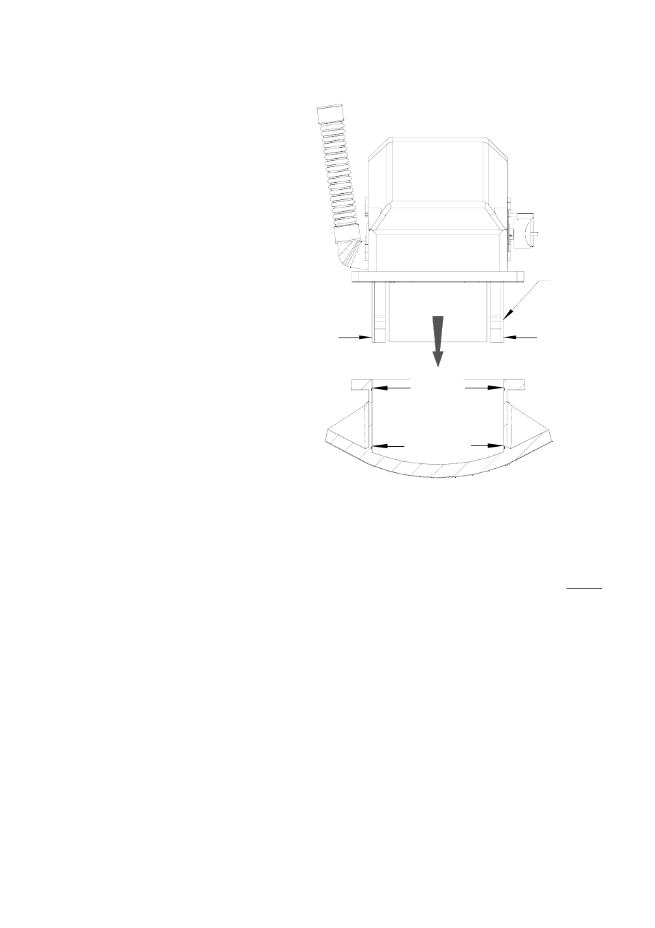
Thruster
Unit
Sliding
Plates
249mm
at top
249mm
at bottom
( d )
( d )
d) The reason for respecting
these dimensions is to avoid
the sliding plates becoming
wedged into mounting base
resulting in the unit getting
stuck in the down position.
e) Before fixing the thruster
unit onto the mounting
base flange it is important to
ensure that the top surface
of the mounting base flange
is perfectly flat to accept the
« O » ring seal of the
Compact Retract base flange
ensuring perfect water
tightness.
3.5
FINAL FITTING OF THE THRUSTER UNIT TO THE MOUNTING BASE
a) Make sure you provide sufficient access underneath the flange to allow for tightening the nuts. If
access is not possible, provide a special mounting flange with metric studs or tapped holes. The
bolts fixing the thruster onto the mounting flange must be inserted from top to bottom, except
for the four bolts on the bow side of the flange, which should be inserted from the bottom to
the top.
b) Final installation of the thruster unit onto the mounting base must be made after thoroughly
cleaning and then liberally coating both joint surfaces (thruster base flange and mounting base
flange) with good quality marine grease, to ensure “O”-ring seal is compressed flat, evenly,
smoothly and squarely when the bolts are tightened.
c) Under no circumstances should the thruster be glued or bedded down with a marine type
mastic/glue such as Sikaflex or other similar product(s).
d) The flange bolts should be tightened sequentially and in successive passes until the two surfaces
touch.
8