System description – PowerWalker VI 750R User Manual
Page 9
3. SYSTEM DESCRIPTION
10. PCB FAIL LED(or SITE FAULT LED):
PCB FAIL LED: the LED indicator will light on when the power module
of UPS fails.
SITE FAULT LED: the LED indicator will light on when UPS is plugged
into an improperly utility
Note: “SITE FAULT” function is only available for 120Vac models.
11. BAT Mode LED (Battery Mode):
The LED indicator will flash every five seconds when the UPS is providing
battery power to your equipment. On the other hand, the LED indicator
gives you a warning which will flash every two seconds when the battery is
low.
12. Line Mode LED:
The line LED indicator illuminates when the AC source is present.
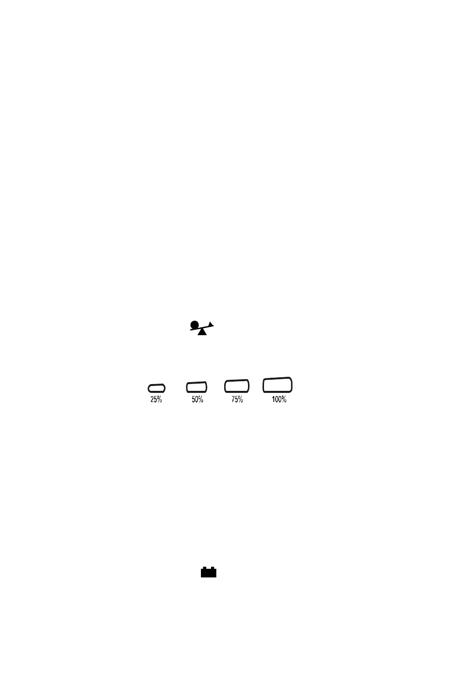
13. Capacity of Load LED:
Load Indicator: The
LED indicator and the load level indicator
will illuminate to show the load level.
Load Level Indicator:
There are four LED bar graphic to indicate the percentage of UPS
load capacity which is being used by the protected equipment. The
greater the load, the more LED indicators that will be illuminated.
Each LED indicator designates a 25% of the UPS output capacity.
Please see the following load level respectively.
0 ~ 25%: 1
st
LED indicator
26% ~ 50%: 1
st
and 2
nd
LEDs indicator
51% ~ 75% : 1
st
, 2
nd
, and 3
rd
LEDs indicator
76% ~ 100%: All of four LED indicators will illuminate
14. Capacity of Battery LED:
Battery Indicator: The
LED indicator and battery level indicator
will illuminate to show battery level.
9