GlowShift Tinted Series Boost_Air Fuel Combo Gauge User Manual
Tinted series - boost / air fuel combo gauge
Tinted Series - Boost / Air Fuel Combo Gauge
For Product Number: GS-TC02
Wire Color Code
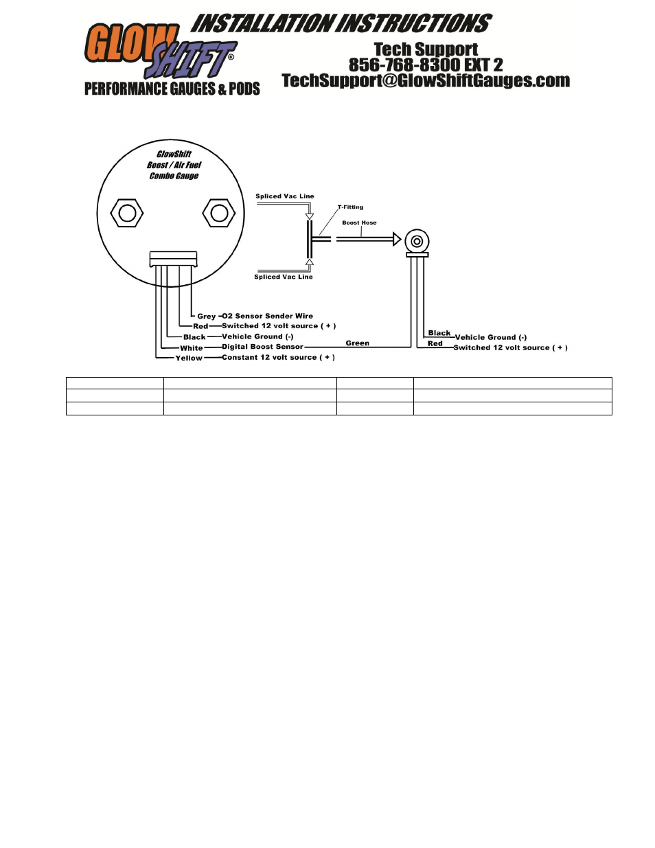
Black
Engine / Chassis Ground
Gray
Stock Oxygen Sensor
Red
12v Ignition Switch (+)
White
Electronic Boost Sensor (white wire)
Yellow
Constant 12 volt (+)
1. Disconnect the negative battery cable.
2. Using automotive grade wiring (18 gauge), connect
the red wire from the gauge and digital boost sensor to
a positive 12 volt ignition (switched) source. It may be
connected to the fuse panel, an accessory wire, or any
positive 12 volt source that turns on and off with the
ignition switch of the vehicle.
If wiring to an un-fused source, install a 3 amp
fuse inline within 20 inches of the sources
connection. You may obtain an optional “add a
circuit” accessory. This component easily fits
into your fuse panel and provides an additional
fused power wire for accessories such as
gauges. This is available at www.GlowShift.com
or a local auto parts store.
3. Connect the yellow wire to a positive 12 volt constant
(un-switched) source either directly to the battery or to a
fuse panel on the vehicle. If wiring to an un-fused
source, install a 3 amp fuse inline within 20 inches of
the sources connection.
4. Air / Fuel Ratio: Connect the gray wire to the
vehicle Oxygen sensor signal. You may connect directly
to the ECU harness or splice into the signal wire leaving
the sensor. This is usually the gray wire on the Oxygen
Sensor. (0v ~ 1v - NARROW BAND SIGNAL ONLY)
5. Boost: Cut any vacuum line and insert the included t-fitting
between the 2 cut pieces of vacuum line. Insert accordingly so
that the intersecting cross piece of the fitting is left to be
connected to the boost hose. Route and connect the boost hose to
the digital boost sensor.
If a vacuum line is not available to cut, you may need to
purchase a brass barbed fitting to install into the intake
manifold to obtain a boost pressure reading. Fittings can
be purchased at www.GlowShift.com an authorized
dealer.
Make sure the digital boost sensor is mounted in dry safe
area either inside the cabin or engine bay.
6. Connect the boost hose line to the Digital Boost Sensor and
connect the white boost sensor wire to the white wire on the
gauge wire harness.
7. Connect the black wire from the gauge and the black wire
from the digital boost sensor, to any good (unpainted) ground
connection. You may also route a wire directly to the negative
side of the vehicle’s battery.
8. Reconnect the negative battery cable.
This gauge should never be connected to a dimmer.
Connecting the gauge to any type of dimmer switch unit will
cause the gauge to improperly function.