Rainbow Electronics br9080af-w User Manual
Page 9
BR9080AF-W / BR9080ARFV-W / BR9080ARFVM-W /
Memory ICs
BR9016AF-W / BR9016ARFV-W / BR9016ARFVM-W
9/12
(5) READY / BUSY display
(R / B pin and DO pin: BR9080AF-W / ARFV-W / ARFVM-W, BR9016AF-W / ARFV-W / ARFVM-W)
1) This display outputs the internal status signal; the R / B pin outputs the HIGH or LOW status at all times. The display
can also be output from the DO pin. Following completion of the writing command, if CS falls while SK is LOW, either
HIGH or LOW is output. (The display can also be output without using the R / B pin, leaving it open.)
2) When writing data to a memory cell, the READY / BUSY display is output from the rise of the 32nd clock pulse of the
SK signal after tSV, from the R / B pin.
R / B display = LOW: writing in progress
(The internal timer circuit is activated, and after the tE / W timing has been created, the timer circuit stops automatically.
Writing of data to the memory cell is done during the tE / W timing, during which time other commands cannot be
received.)
R / B display = HIGH: command standby state
(Writing of data to the memory cell has been completed and the next command can be received.)
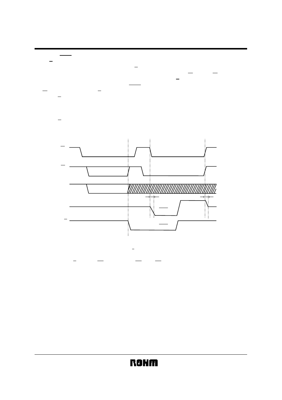
Fig.8 R / B Status Output timing chart
SK
CS
DI
DO
READY
READY
READY
BUSY
t
PD
t
OH
BUSY
Write command
Clock
R / B
HIGH-Z
HIGH-Z
1) DO will output R / B status after CS is held low during SK=L, until CS is held high.
Note : The document may be strategic technical data subject to COCOM regulations.