Chip information, Pin configuration – Rainbow Electronics MAX1448 User Manual
Page 16
MAX1448
10-Bit, 80Msps, Single +3.0V, Low-Power
ADC with Internal Reference
16
______________________________________________________________________________________
Total Harmonic Distortion (THD)
THD is typically the ratio of the RMS sum of the input
signal’s first five harmonics to the fundamental itself.
This is expressed as:
where V
1
is the fundamental amplitude, and V
2
through
V
5
are the amplitudes of the 2nd- through 5th-order
harmonics.
Spurious-Free Dynamic Range (SFDR)
SFDR is the ratio expressed in decibels of the RMS
amplitude of the fundamental (maximum signal compo-
nent) to the RMS value of the next largest spurious
component, excluding DC offset.
Intermodulation Distortion (IMD)
The two-tone IMD is the ratio expressed in decibels of
either input tone to the worst 3rd-order (or higher) inter-
modulation products. The individual input tone levels
are at -6.5dB full scale, and their envelope is at -0.5dB
full scale.
___________________Chip Information
TRANSISTOR COUNT: 5684
PROCESS: CMOS
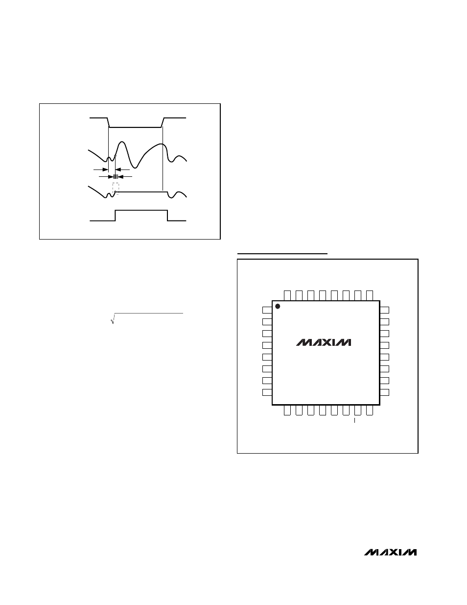
HOLD
ANALOG
INPUT
SAMPLED
DATA (T/H)
T/H
t
AD
t
AJ
TRACK
TRACK
CLK
Figure 10. Track-and-Hold Aperture Timing
THD
V
V
V
V
V
=
×
+
+
+
(
)
20
1
2
2
3
2
4
2
5
2
log
(
) /
MAX1448
TQFP
TOP VIEW
32
28
29
30
31
25
26
27
REFIN
GND
REFOUT
D0
REFP
D1
D2
D3
10
13
15
14
16
11
12
9
V
DD
GND
V
DD
PD
CLK
OE
GND
D9
17
18
19
20
21
22
23
OGND
24
D4
T.P.
OV
DD
D5
D6
D7
D8
2
3
4
5
6
7
8
GND
IN-
IN+
GND
GND
V
DD
COM
1
REFN
Pin Configuration