Rainbow Electronics MAX1448 User Manual
General description, Applications, Features
General Description
The MAX1448 +3V, 10-bit analog-to-digital converter
(ADC) features a fully differential input, a pipelined 10-
stage ADC architecture with wideband track-and-hold
(T/H), and digital error correction incorporating a fully
differential signal path. The ADC is optimized for low-
power, high dynamic performance in imaging and digi-
tal communications applications. The converter
operates from a single +2.7V to +3.6V supply, consum-
ing only 120mW while delivering a 59dB (typ) signal-to-
noise ratio (SNR) at a 20MHz input frequency. The fully
differential input stage has a -3dB 400MHz bandwidth
and may be operated with single-ended inputs. In addi-
tion to low operating power, the MAX1448 features a
5µA power-down mode for idle periods.
An internal +2.048V precision bandgap reference is
used to set the ADC full-scale range. A flexible refer-
ence structure allows the user to supply a buffered,
direct, or externally derived reference for applications
requiring increased accuracy or a different input volt-
age range.
Lower speed, pin-compatible versions of the MAX1448
are also available. Please refer to the MAX1444 data
sheet for a 40Msps version and to the MAX1446 data
sheet for a 60Msps version.
The MAX1448 has parallel, offset binary, CMOS-com-
patible three-state outputs that can be operated from
+1.7V to +3.6V to allow flexible interfacing. The device
is available in a 5mm x 5mm 32-pin TQFP package and
is specified over the extended industrial (-40°C to
+85°C) temperature range.
________________________Applications
Ultrasound Imaging
CCD Imaging
Baseband and IF Digitization
Digital Set-Top Boxes
Video Digitizing Applications
Features
♦ Single +3.0V Operation
♦ Excellent Dynamic Performance
59dB SNR at f
IN
= 20MHz
74dBc SFDR at f
IN
= 20MHz
♦ Low Power
40mA (Normal Operation)
5µA (Shutdown Mode)
♦ Fully Differential Analog Input
♦ Wide 2V
p-p
Differential Input Voltage Range
♦ 400MHz -3dB Input Bandwidth
♦ On-Chip +2.048V Precision Bandgap Reference
♦ CMOS-Compatible Three-State Outputs
♦ 32-Pin TQFP Package
MAX1448
10-Bit, 80Msps, Single +3.0V, Low-Power
ADC with Internal Reference
________________________________________________________________ Maxim Integrated Products
1
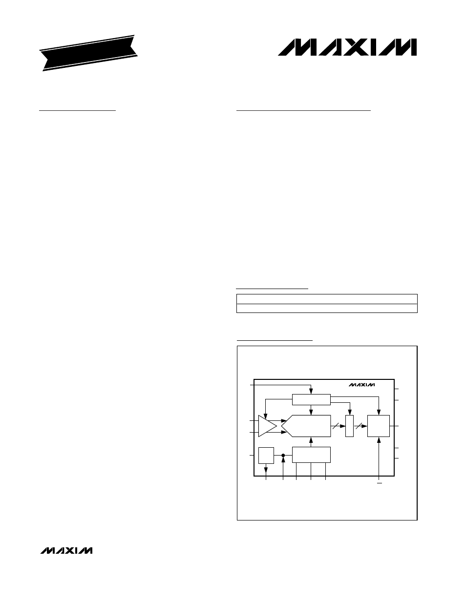
CLK
IN+
CONTROL
10
PIPELINE ADC
REF SYSTEM +
BIAS
OUTPUT
DRIVERS
D
E
C
REF
REFIN
REFOUT
REFP
COM REFN
OE
V
DD
GND
OV
DD
OGND
D9–D0
IN-
PD
T/H
MAX1448
Functional Diagram
19-5400; Rev 0; 9/00
For free samples and the latest literature, visit www.maxim-ic.com or phone 1-800-998-8800.
For small orders, phone 1-800-835-8769.
EVALUATION KIT
AVAILABLE
Ordering Information
Pin Configuration appears at end of data sheet.
PART
TEMP. RANGE
PIN-PACKAGE
MAX1448EHJ
-40
°C to +85°C
32 TQFP