Rainbow Electronics MAX1448 User Manual
Page 14
MAX1448
10-Bit, 80Msps, Single +3.0V, Low-Power
ADC with Internal Reference
14
______________________________________________________________________________________
using a split ground plane arranged to match the physi-
cal location of the analog ground (GND) and the digital
output driver ground (OGND) on the ADC's package.
The two ground planes should be joined at a single
point so that the noisy digital ground currents do not
interfere with the analog ground plane. The ideal loca-
tion of this connection can be determined experimen-
tally at a point along the gap between the two ground
planes that produces optimum results. Make this con-
nection with a low-value, surface-mount resistor (1
Ω to
5
Ω), a ferrite bead, or a direct short. Alternatively, all
ground pins could share the same ground plane if the
ground plane is sufficiently isolated from any noisy, dig-
ital systems ground plane (e.g., downstream output
buffer or DSP ground plane). Route high-speed digital
signal traces away from sensitive analog traces. Keep
all signal lines short and free of 90° turns.
Static Parameter Definitions
Integral Nonlinearity
Integral nonlinearity (INL) is the deviation of the values
on an actual transfer function from a straight line. This
straight line can be either a best straight-line fit or a line
drawn between the endpoints of the transfer function
once offset and gain errors have been nullified. The
MAX1448’s static linearity parameters are measured
using the best straight-line fit method.
INPUT
300
Ω
-5V
+5V
0.1
µF
0.1
µF
0.1
µF
C
IN
22pF
C
IN
22pF
R
ISO
50
Ω
R
ISO
50
Ω
-5V
600
Ω
300
Ω
300
Ω
IN+
IN-
LOWPASS FILTER
COM
600
Ω
+5V
-5V
0.1
µF
600
Ω
300
Ω
600
Ω
300
Ω
0.1
µF
0.1
µF
0.1
µF
+5V
0.1
µF
300
Ω
MAX4108
MAX1448
MAX4108
MAX4108
LOWPASS FILTER
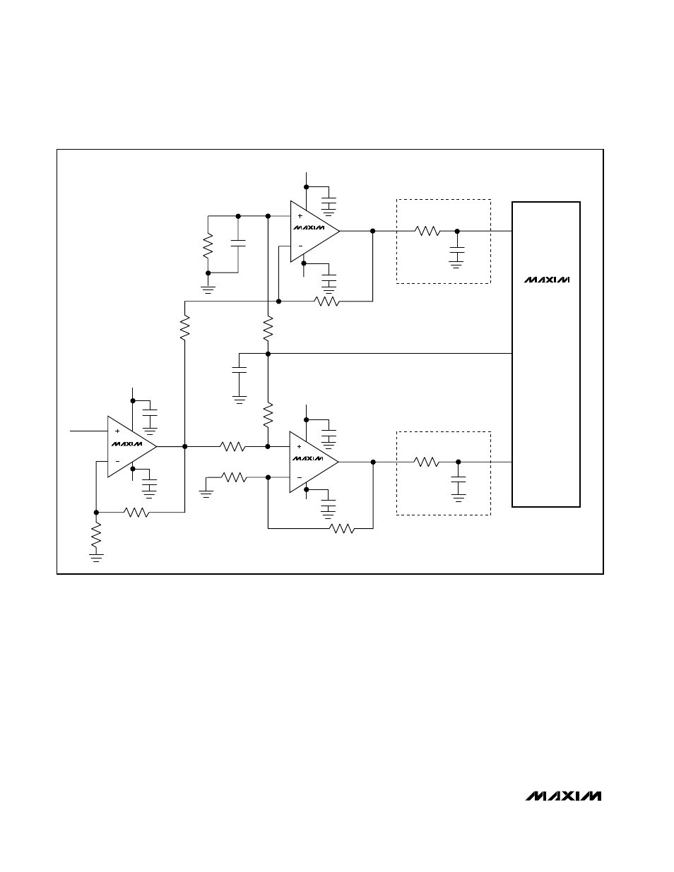
Figure 7. Typical Application Circuit Using the Internal Reference