Table 1. data format (two’s complement) – Rainbow Electronics MAX1669 User Manual
Page 9
MAX1669
Fan Controller and Remote Temperature Sensor
with SMBus Serial Interface
_______________________________________________________________________________________
9
mode, the ALERT and OVERT outputs respond correct-
ly according to the last valid A/D result.
Note that the ALERT output does not respond to T
CRIT
(OVERT) comparisons.
The OVERT latch can implement an override control to
the FAN output, which forces the fan to V
CC
whenever
the T
CRIT
threshold is crossed. This override switch is
the backup fan control loop, and is enabled through the
FAN ON bit in the configuration register (bit 2). Note
that changing the duty to 100% in this way doesn’t
affect the contents of the DUTY register, and the FAN
output reverts to the preprogrammed duty factor (or
DAC voltage) when the OVERT latch is reset.
Diode Fault Alarm
A continuity fault detector at DXP detects whether the
remote diode has an open-circuit condition, short-cir-
cuit to GND, or short-circuit DXP-to-DXN condition. At
the beginning of each conversion, the diode fault is
checked and the status byte updated. This fault detec-
tor is a simple voltage detector; DXP rising above V
CC
-
1V or falling below DXN + 40mV constitutes a fault con-
dition. Also, if the ADC has an extremely low differential
input voltage, the diode is assumed to be shorted and
a fault occurs. Note that the diode fault isn’t checked
until a conversion is initiated, so immediately after
power-on reset the status byte indicates no fault is pre-
sent even if the diode path is broken. Any diode fault
will return a +127°C fault reading and cause ALERT to
go low.
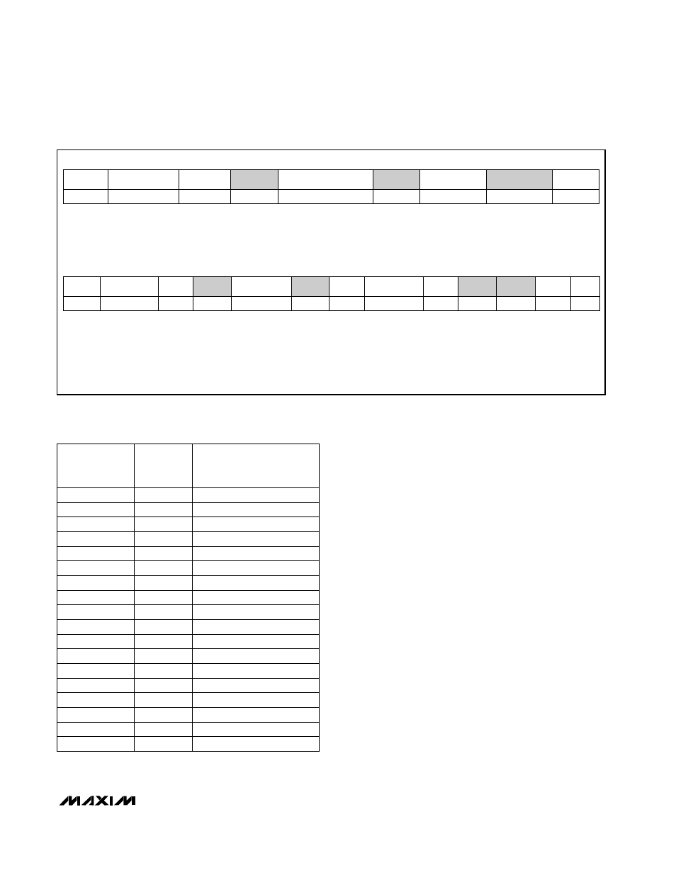
Write Byte Format
Read Byte Format
7-bit slave address:
equivalent to chip-select line
Command byte: selects which
register you are writing to
Data byte: data goes into the register
set by the command byte (to set
thresholds, configuration masks, and
sampling rate)
Slave address:
equivalent to chip-select
line
Command byte: selects
which register you are
reading from
Slave address: repeated
due to change in data-
flow direction
Data byte: reads from
the register set by the
command byte
S = Start condition
Shaded = Slave transmission
P = Stop condition
A
= Not acknowledged
Figure 3. SMBus Protocols
S
1
WR
1
ACK
1
COMMAND
8 bits
ACK
1
S
1
ADDRESS
7 bits
RD
1
ACK
1
DATA
8 bits
A
1
P
1
1
S
ADDRESS
7 bits
1
WR
ACK
1
8 bits
COMMAND
ACK
1
8 bits
DATA
ACK
1
1
P
TEMP (°C)
ROUNDED
TEMP (°C)
+0.25
+0
+0.50
+1
+25.25
+25
+126.00
+126
+0.00
+0
-0.25
+0
-0.50
+0
-0.75
-1
+127.00
+130.00
+127
+127
+126.50
+127
-1.00
-1
-25.00
-25
-25.50
-26
-54.75
-55
-55.00
-55
-65.00
-65
-70.00
-65
DIGITAL OUTPUT
DATA BITS
SIGN MSBs
LSBs
1 111
1111
0
000
0000
1 110
0111
0
000
0001
0 001
1001
0 111
1110
0 000
0000
0 000
0000
1 110
0110
1 100
1001
0 000
0000
1
111
1111
1
100
1001
1
011
1111
1
011
1111
0
111
1111
0 111
1111
0 111
1111
Table 1. Data Format (Two’s Complement)
ADDRESS
7 bits