Max1669, Applications information, Table 12. component manufacturers – Rainbow Electronics MAX1669 User Manual
Page 16
MAX1669
Power-Up Defaults
• Interrupt latch is cleared.
• ADC begins autoconverting at a 2Hz rate.
• Command byte is set to 01h to facilitate quick
remote receive-byte queries.
• T
HIGH
and T
LOW
registers are set to +127°C and
-55°C limits, respectively.
• T
CRIT
register is set to +100°C.
• ALERT and OVERT are reset to high-Z state.
• Device is in low-frequency PWM mode, 20Hz setting.
• PWM output is off (duty factor set to 0%).
• I/O1, I/O2 are high-Z (configured as inputs).
__________Applications Information
Remote Diode Selection
Temperature accuracy depends on having a good-
quality, diode-connected, small-signal transistor.
Accuracy has been experimentally verified for all of the
devices listed in Table 12. The MAX1669 can also
directly measure the die temperature of CPUs and
other ICs having on-board temperature-sensing diodes,
such as the Intel Pentium II.
The transistor must be a small-signal type having a rel-
atively high forward voltage; otherwise, the A/D input
voltage range can be violated. The forward voltage
must be greater than 0.25V at 10µA; check to ensure
this is true at the highest expected temperature. The
forward voltage must be <0.95V at 100µA; check to
ensure this is true at the lowest expected temperature.
Do not use large power transistors. Also, ensure that
the base resistance is <100
Ω. Tight specifications for
forward-current gain (+50 to +150, for example) indi-
cate that the manufacturer has good process controls
and the devices have consistent V
BE
characteristics.
Series resistance causes +1/2°C error per ohm. When
monitoring the temperature of a remote unit’s internal
diode, ensure that trace series resistance does not
introduce significant error.
ADC Noise Filtering
The ADC is an integrating type with inherently good
noise rejection, especially of low-frequency signals
such as 60Hz/120Hz power-supply hum. Micropower
operation places constraints on high-frequency noise
rejection; therefore, careful PC board layout and proper
external noise filtering is required for high-accuracy
remote measurements in electrically noisy environ-
ments.
High-frequency EMI is best filtered at DXP and DXN
with an external 2200pF capacitor. This value can be
increased to about 3300pF (max), including cable
capacitance. Capacitance higher than 3300pF intro-
duces errors due to the rise time of the switched-cur-
rent source.
Nearly all noise sources tested cause the ADC mea-
surements to be higher than the actual temperature,
typically by +1°C to +10°C, depending on frequency
and amplitude (see Typical Operating Characteristics).
FAN Application Circuits
In PWM mode, the output impedance at FAN is <50
Ω,
enabling it to drive an N-channel MOSFET as shown in
the Typical Operating Circuit. Return the source of the
N-channel MOSFET to the system power ground, away
from the ground of the MAX1669. For 3.3V applications,
use low-threshold N-channel MOSFETs (Table 1).
In DAC mode, the FAN output can be linearly controlled
(Figure 5). Upon power-up, the fan is off. The N-channel
MOSFET is biased at the threshold of turning on. As
V
FAN
rises, the fan turns on linearly. To have the fan
turned on at power-up, use the circuit shown in Figure 6.
Fan Controller and Remote Temperature Sensor
with SMBus Serial Interface
16
______________________________________________________________________________________
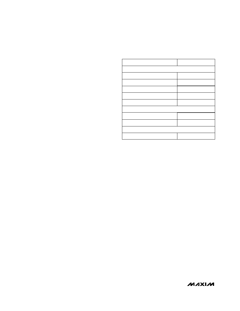
Table 12. Component Manufacturers
Note: Transistors must be diode-connected (base shorted to
collector).
MMBT3906
KST3906
MANUFACTURER
MODEL NUMBER
SOT23 BJT
Central Semiconductor (USA)
CMPT3906
Fairchild Semiconductor (USA)
MMBT3906
Rohm Semiconductor (Japan)
SST3906
Samsung (Korea)
MOSFET N-CHANNEL
International Rectifier (USA)
IRF7201
MOSFET P-CHANNEL
International Rectifier (USA)
IRF7205
Motorola (USA)
MMBT3906
Fairchild Semiconductor (USA)
FDN359AN