Table 9. status byte bit assignments – Rainbow Electronics MAX1669 User Manual
Page 15
Slave Addresses
The MAX1669 appears to the SMBus as one device
having a common address for the temperature sensor
section, GPIO section, and fan-control section. The
device address can be set to one of eight different val-
ues by pin-strapping ADD_ pins so that more than one
MAX1669 can reside on the same bus without address
conflicts (Table 11).
The MAX1669 also responds to the SMBus Alert
Response slave address (see the Alert Response
Address section).
POR and UVLO
The MAX1669’s memory is volatile. To prevent ambigu-
ous power-supply conditions from corrupting the data
in memory and causing erratic behavior, a POR voltage
detector monitors V
CC
and clears the memory if V
CC
falls below 1.85V (typical, see the Electrical Character-
istics table). When power is first applied and V
CC
rises
above 1.9V (typ), the logic blocks begin operating;
although reads and writes at V
CC
levels below 3V are
not recommended. A second V
CC
comparator, the
ADC UVLO comparator, prevents the ADC from con-
verting until there is sufficient headroom (V
CC
= 2.8V typ).
MAX1669
Fan Controller and Remote Temperature Sensor
with SMBus Serial Interface
______________________________________________________________________________________
15
4
TRAN2*
This bit is set if a low-to-high or high-to-low transition has occurred at I/O2 (regardless of the
state of the mask bits).
3
RHIGH*
A high indicates that the high-temperature alarm has activated
This bit is set if a low-to-high or high-to-low transition has occurred at I/O1 (regardless of the
state of the mask bits).
TRAN1*
5
BIT
This bit indicates the current state of I/O2 (unlatched).
I/O2
6
This bit indicates the current state of I/O1 (unlatched).
I/O1
7
(MSB)
FUNCTION
NAME
1
DIODE
A high indicates a remote-diode fault (open-circuit, shorted diode, or DXP short to GND).
0 (LSB)
OVERT
When the T
CRIT
threshold is crossed, this bit goes high. The polarity of this bit does not depend
on the POL bit (bit 5 in configuration byte).
A high indicates that the low-temperature alarm has activated.
RLOW*
2
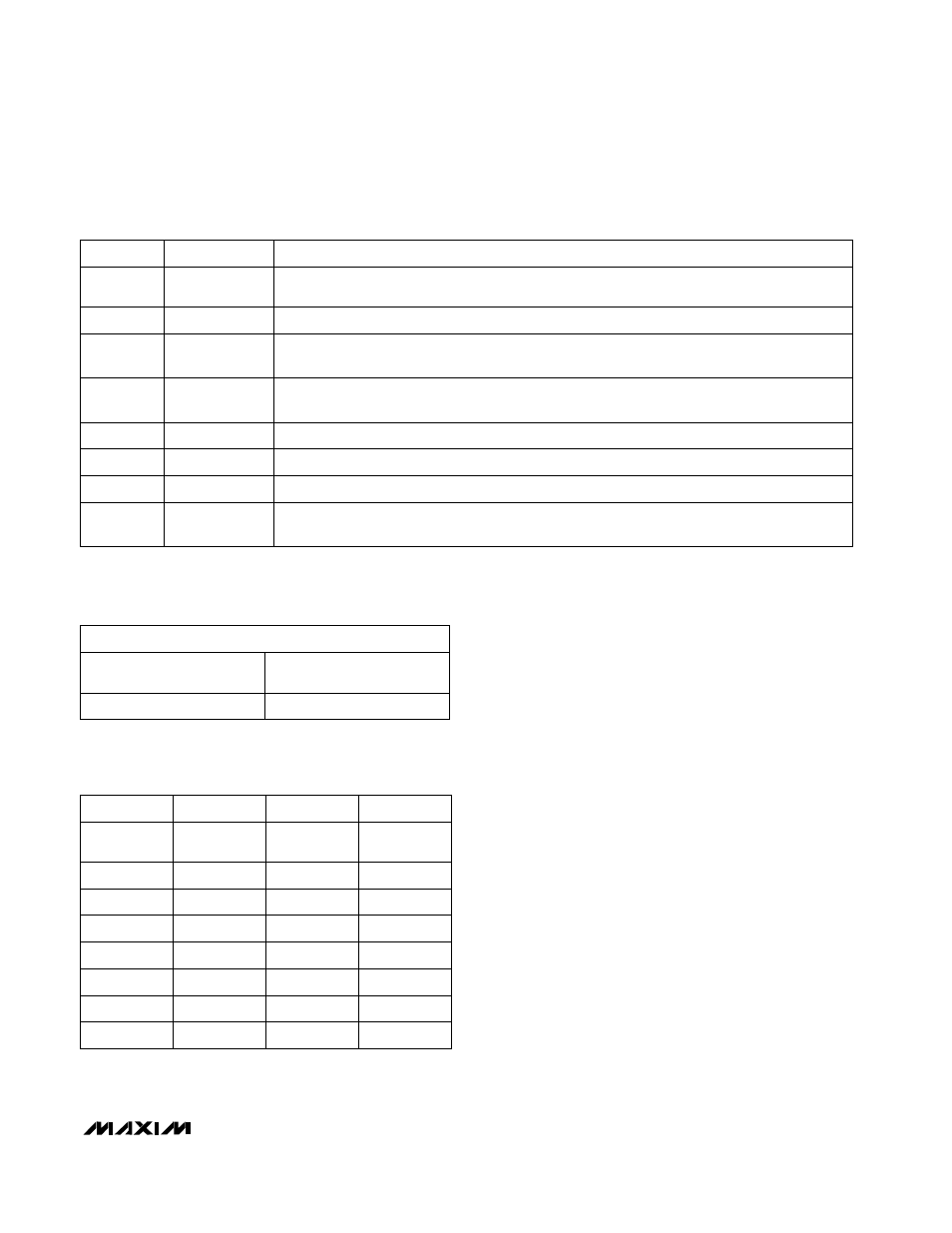
Table 9. Status Byte Bit Assignments
*TRAN1 and TRAN2 alarm flags stay high until cleared by POR or until the status byte register is read. RHIGH and RLOW alarm
flags stay high until cleared by POR or the temperature fault is removed and the status byte is read.
0000 0000
0000 0101
MS BYTE
LSBs MSBs
LS BYTE
LSBs MSBs
MAX1669 ID CODE
Table 10. Device ID Code
Table 11. Slave Address Decoding
(ADD_ Pins)
ADD0
V
CC
GND
GND
GND
GND
GND
ADD1
ADD2
ADDRESS
0011 001b
0011 000b
GND
V
CC
GND
0011 010b
GND
V
CC
V
CC
0101 001b
V
CC
GND
GND
0101 010b
V
CC
GND
V
CC
0101 011b
V
CC
V
CC
GND
1001 100b
V
CC
V
CC
V
CC
1001 101b