Detailed description – Rainbow Electronics MAX1611 User Manual
Page 8
_______________Detailed Description
Getting Started
A cold-cathode fluorescent lamp (CCFL) has two termi-
nals. For the CCFL to emit light, the two lamp terminals
must be driven with a high-voltage (approximately
550V AC RMS) and high-frequency (approximately
45kHz) sine wave. The MAX1610/MAX1611 use a vary-
ing DC input voltage to create this high-voltage, high-
frequency sine-wave drive. To select the correct
component values for the MAX1610/MAX1611 circuit,
several CCFL parameters and the minimum DC input
voltage must be specified; these are listed in Table 1.
Table 3 shows the recommended component values to
use with the circuit of Figure 4, depending on the par-
ticular CCFL parameters. The C2 values in Table 3
have been selected such that the normal operating
voltage on the secondary of T1 is as close as possible
to the CCFL strike voltage (where the strike voltage
(V
S
) is assumed to be approximately 1.8 times the
CCFL operating voltage (V
L
)).
Components T1, C1, R2, Q1, and Q2 form a Royer
oscillator. A Royer oscillator is a resonant tank circuit
that oscillates at a frequency dependent on C1, the pri-
mary magnetizing inductance of T1 (L
P
), and the
impedance seen by the T1 secondary. The
MAX1610/MAX1611 regulate the current fed into the
Royer oscillator by sensing the voltage on R1. For a
given current through the Royer oscillator (I
R1
), the
power delivered to the CCFL depends on the Royer
oscillator frequency. The R1 values in Table 3 have
been selected to ensure that the power into the CCFL
does not exceed its maximum rating, despite T1, C1, and
C2 component-value variations. The Royer oscillator
waveforms for the circuit of Figure 4 are shown in Figures
5 and 6.
Analog Circuitry
The MAX1610/MAX1611 maintain fixed CCFL bright-
ness with varying input voltages on BATT by regulating
the current fed into the Royer oscillator. This current is
sensed via resistor R1 between CSAV and GND. An
internal switch from BATT-to-LX pulse-width modulates
at a fixed frequency to servo the CSAV pin to its regula-
tion voltage. The CSAV regulation voltage can be
adjusted via the digital interface to set CCFL bright-
ness. The MAX1610 and MAX1611 differ only in the
digital interface they use to adjust the internal 5-bit digi-
tal-to-analog converter (DAC) that sets the CSAV regu-
lation voltage. The minimum-scale (min-scale) CSAV
regulation voltage is resistor adjustable using the MIN-
DAC pin, setting the minimum CCFL brightness. The
D/A setting at MAX1610/MAX1611 power-up is preset
to mid-scale (10000 binary) (Figure 7).
MINDAC Sets the Minimum Scale
The MINDAC pin sets the lowest CCFL brightness
level. The voltage at MINDAC is divided by eight, and
sets the minimum CSAV regulation voltage. For exam-
ple, in the circuit of Figure 4, R5 (150k
Ω
) and R6
(51k
Ω
) form a resistor divider from REF, which sets
MINDAC to 507mV (REF = 2.0V). This sets a minimum
CSAV regulation voltage of 63mV with a full-scale
CSAV regulation voltage of 247mV.
MAX1610/MAX1611
Digitally Controlled CCFL Backlight
Power Supplies
8
_______________________________________________________________________________________
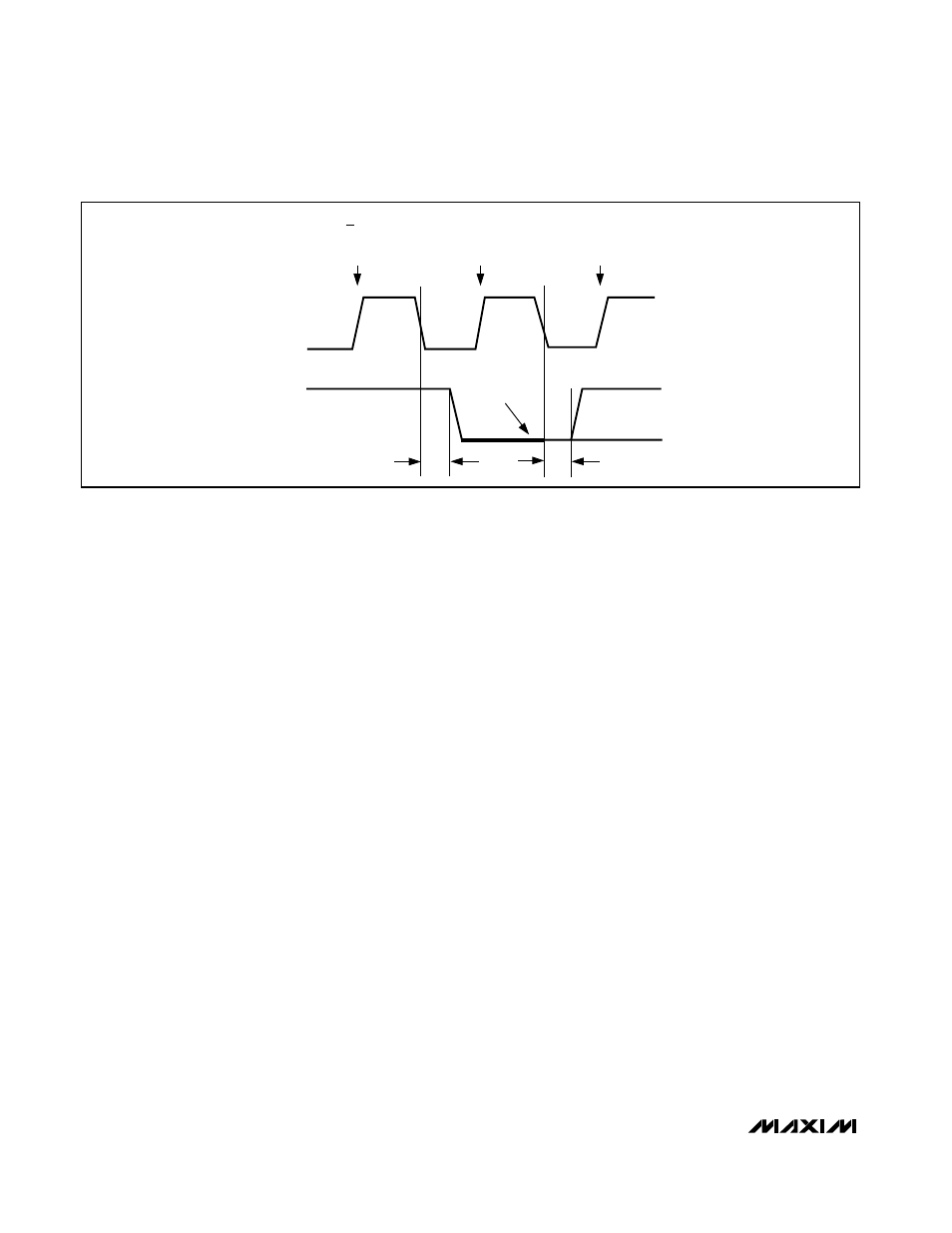
t
DV
t
DV
SCL
RW BIT
CLOCKED
INTO SLAVE
ACKNOWLEDGED
BIT CLOCK
INTO MASTER
MOST SIGNIFICANT
BIT CLOCKED
SLAVE PULLING
SDA LOW
SDA
• • •
• • •
Figure 3. MAX1611 SMB Serial-Interface Timing—Acknowledge