Digitally controlled ccfl backlight power supplies, Max1610 digital interface, Max1611 digital interface – Rainbow Electronics MAX1611 User Manual
Page 14
MAX1610/MAX1611
switching frequency. Any rising edge on SYNC restarts
a BATT-to-LX switch cycle by forcing the switch on.
________MAX1610 Digital Interface
The MAX1610 contains an internal 5-bit up/down counter
that sets the value of the internal 5-bit DAC. At power-on,
or when both the UP and DN pins are held high simulta-
neously, the 5-bit up/down counter is preset to 10000
binary, which corresponds to mid-scale. A rising edge
on UP increments the 5-bit up/down counter. A rising
edge on DN decrements the 5-bit up/down counter. The
counter will not roll over on either underflow or overflow.
For example, if the CCFL is at maximum intensity level,
rising edges on UP will not change the output.
The
SHDN pin provides a way to lower the MAX1610
supply current to 10µA without resetting the 5-bit
up/down counter. With
SHDN = 1, the MAX1610 oper-
ates normally with VL at 4.5V. When the BATT-to-LX
power switch operates, an additional 3mA of current
(other than the supply current) is consumed through
the BST pin, requiring VL to source at least 4.5mA of
current. With
SHDN = 0, all analog circuitry turns off,
except for a coarse regulator that can source up to
500µA from VL. The coarse regulator preserves the
state of the internal logic and keeps the digital interface
active during shutdown (
SHDN = 0).
________MAX1611 Digital Interface
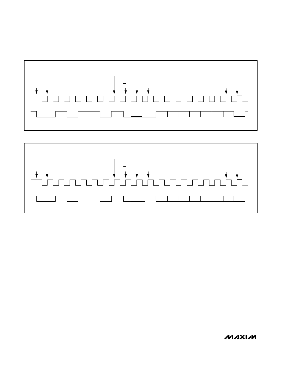
A single byte of data written over the Intel System
Management Bus (SMBus™) controls the MAX1611.
Figures 10 and 11 show example single-byte writes. The
MAX1611 contains two 7-bit latches for storing configu-
ration data. Only one of the 7-bit latches is active at a
time. The MAX1611 responds only to its own address,
0101101 binary. The SMBSUS pin selects which of the
two sets of configuration data is used. Figure 12 shows
a schematic diagram of the MAX1611’s digital circuitry.
Notice that the SMBSUS pin selects which one of the
Digitally Controlled CCFL Backlight
Power Supplies
14
______________________________________________________________________________________
START
CONDITION
MOST
SIGNIFICANT
ADDRESS BIT
LEAST
SIGNIFICANT
ADDRESS BIT
SLAVE PULLS
SDA LOW
SLAVE PULLS
SDA LOW
REGSEL
D4-0
STDBY-0
SHDNB-0
D3-0
D2-0
D1-0
D0-0
SLAVE
ACKNOWLEDGE
SLAVE
ACKNOWLEDGE
MOST
SIGNIFICANT
DATA BIT
LEAST
SIGNIFICANT
DATA BIT
SCL
SDA
R/W BIT
START
CONDITION
MOST
SIGNIFICANT
ADDRESS BIT
LEAST
SIGNIFICANT
ADDRESS BIT
SLAVE PULLS
SDA LOW
SLAVE PULLS
SDA LOW
REGSEL
D4-1
STDBY-1
SHDNB-1
D3-1
D2-1
D1-1
D0-1
SLAVE
ACKNOWLEDGE
SLAVE
ACKNOWLEDGE
MOST
SIGNIFICANT
DATA BIT
LEAST
SIGNIFICANT
DATA BIT
SCL
SDA
R/W BIT
Figure 10. MAX1611 Serial-Interface Single-Byte Write Example (REGSEL = 0)
Figure 11. MAX1611 Serial-Interface Single-Byte Write Example (REGSEL = 1)