Rainbow Electronics MAX1611 User Manual
Page 16
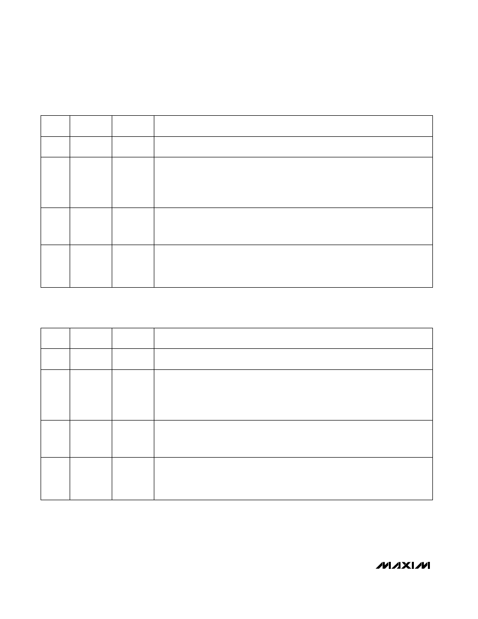
NAME
DESCRIPTION
7
REGSEL
Register Select. A zero in this bit writes the remaining seven bits into the 7-bit latch-0
(Figure 13).
6
SHDNB-0
Complete Shutdown. Pulling SMBSUS low with SHDNB-0 = 0 places the MAX1611 into a
low-quiescent-current shutdown mode, with the reference off and the VL linear-regulator
output switched to a low-current, coarse regulation mode. Pulling SMBSUS low with
SHDNB-0 = 1 puts the MAX1611 into its normal operational mode, with the reference and
internal VL linear regulator fully on. SHDNB-0 supersedes STDBY-0. As long as SHDNB-0 = 0
and SMBSUS = 0, it doesn't matter what STDBY-0 is; the MAX1611 still shuts down.
BIT
5
STDBY-0
Standby, disables CCFL supply only. As long as SMBSUS stays low and STDBY-0 = 0, the
internal power switch is kept off and SS is held shorted to GND; neither the internal refer-
ence nor the linear regulator is affected. With STDBY = 1 and SMBSUS low, the MAX1611
operates normally.
4
3
2
1
0
D4-0
D3-0
D2-0
D1-0
D0-0
DAC Input Data. With the SMBSUS pin low, bits D4-0 through D0-0 set the DAC.
Table 4. MAX1611 Configuration Byte with REGSEL = 0
Table 5. MAX1611 Configuration Byte with REGSEL = 1
POR
STATE*
—
0
0
1
0
0
0
0
* Initial register state after power-up.
* Initial register state after power-up.
MAX1610/MAX1611
Digitally Controlled CCFL Backlight
Power Supplies
16
______________________________________________________________________________________
NAME
DESCRIPTION
7
REGSEL
Register Select. A one in this bit writes the remaining seven bits into the 7-bit latch-1
(Figure 13).
6
SHDNB-1
Complete Shutdown. Pulling SMBSUS high with SHDNB-1 = 0 places the MAX1611 into a
low-quiescent-current shutdown mode, with the reference off and the VL linear regulator
output switched to a low-current coarse regulation mode. Pulling SMBSUS high with
SHDNB-1 = 1 puts the MAX1611 into its normal operational mode, with the reference and
internal VL linear regulator fully on. SHDNB-1 supersedes STDBY-1. As long as SHDNB-1 = 0
and SMBSUS = 0, it doesn’t matter what STDBY-1 is; the MAX1611 still shuts down.
BIT
5
STDBY-1
Standby, disables CCFL supply only. As long as SMBSUS stays high and STDBY-1 = 0,
the internal power switch is kept off and SS is held shorted to GND; neither the internal ref-
erence nor the linear regulator is affected. With STDBY-1 = 1 and SMBSUS high, the
MAX1611 operates normally.
4
3
2
1
0
D4-1
D3-1
D2-1
D1-1
D0-1
DAC Input Data. With the SMBSUS pin high, bits D4-1 through D0-1 set the DAC.
POR
STATE*
—
1
1
1
0
0
0
0