Rainbow Electronics MAX1611 User Manual
Page 2
MAX1610/MAX1611
Digitally Controlled CCFL Backlight
Power Supplies
2
_______________________________________________________________________________________
ABSOLUTE MAXIMUM RATINGS
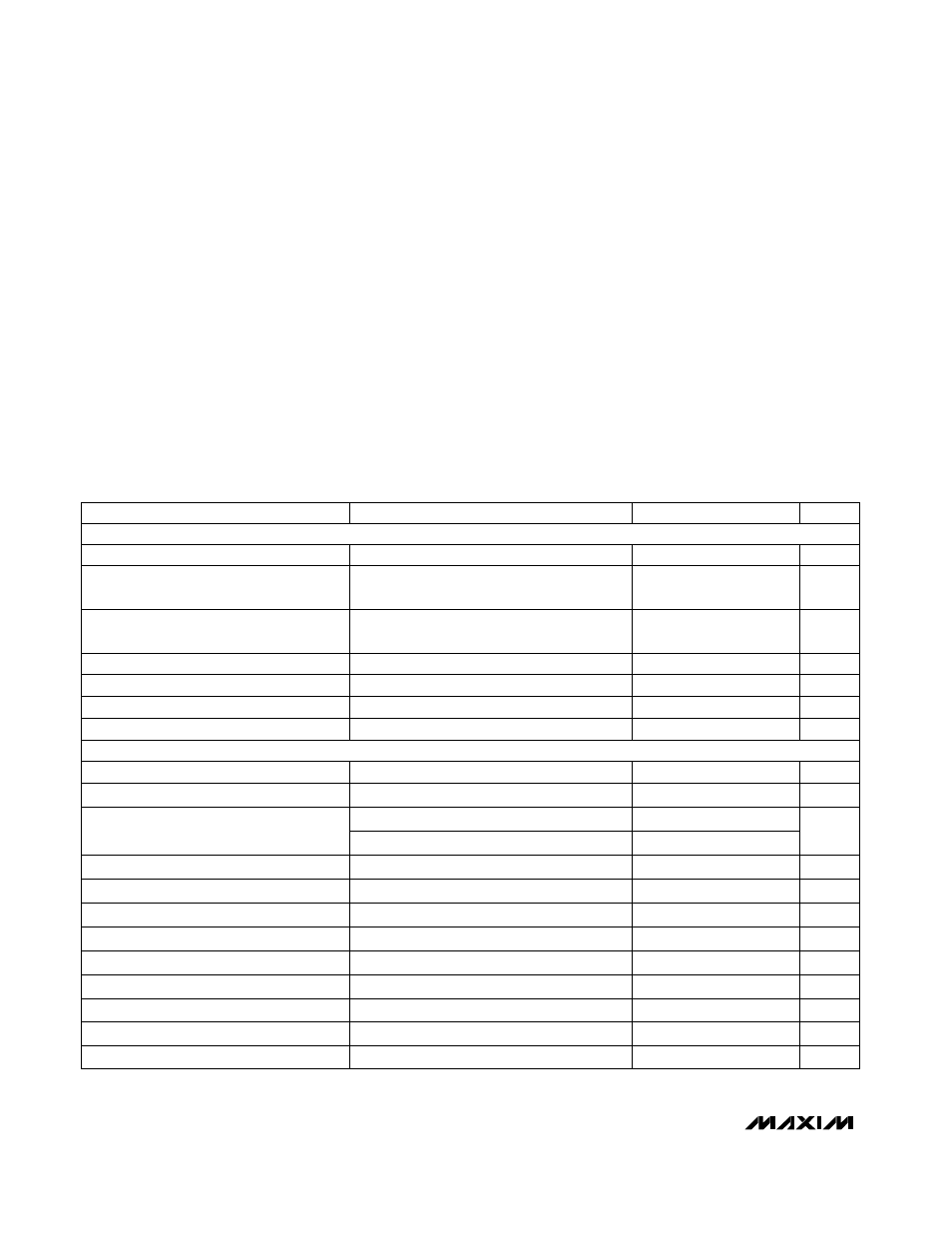
ELECTRICAL CHARACTERISTICS
(T
A
= 0°C to +70°C, BATT = 8.2V, MINDAC = 0V, unless otherwise noted. Typical values are at T
A
= +25°C.)
Stresses beyond those listed under “Absolute Maximum Ratings” may cause permanent damage to the device. These are stress ratings only, and functional
operation of the device at these or any other conditions beyond those indicated in the operational sections of the specifications is not implied. Exposure to
absolute maximum rating conditions for extended periods may affect device reliability.
BATT to GND ............................................................-0.3V to 28V
BST to GND ..............................................................-0.3V to 30V
BST to LX ....................................................................-0.3V to 6V
LX to GND ................................................-0.6V to (BATT + 0.3V)
VL to GND...................................................................-0.3V to 6V
CS, CSAV, CC, SYNC, REF, MINDAC,
SS, OTP to GND............................................-0.3V to (VL + 0.3V)
SHDN, UP, DN to GND ...............................................-0.3V to 6V
SMBSUS, SDA, SCL to GND ......................................-0.3V to 6V
BATT, LX Current .....................................................................1A
SDA Current ........................................................................50mA
VL Current ...........................................................................50mA
Continuous Power Dissipation (T
A
= +70°C)
SO (derate 8.70mW/°C above +70°C) .........................696mW
Operating Temperature Range
MAX1610CSE/MAX1611CSE ..............................0°C to +70°C
Storage Temperature Range .............................-65°C to +160°C
Lead Temperature (soldering, 10sec) .............................+300°C
SYNC = REF
SYNC = GND or VL
CONDITIONS
%
89
91
Power-Switch Maximum Duty Cycle
V
4.0
SYNC Input High Voltage
V
0.5
SYNC Input Low Voltage
µ
A
-1
1
SYNC Input Current
ns
200
BATT = 25V
SYNC Low Pulse Width
ns
200
SYNC High Pulse Width
kHz
240
350
Oscillator SYNC Pin Synchronization Range
kHz
125
145
165
4.75V < BATT < 26V
Oscillator Frequency
250
290
330
µ
A
10
No load
LX Switch Off-Leakage Current
Ω
0.7
1.0
I
SOURCE
= 100
µ
A
BATT-to-LX Switch On-Resistance
SWITCHING REGULATOR
BST - LX = 4.1V
BATT Input Voltage Range
V
4.75
26
SUPPLY AND REFERENCE
SYNC = REF
mV
6
20
SYNC = GND
REF Load Regulation
V
1.92
2.0
2.08
REF Output Voltage
V
3.0
3.6
4.75
VL Output Voltage, Shutdown Mode
V
4.25
4.5
4.75
VL Output Voltage, Operate Mode
mA
1.5
3
BATT Quiescent Supply Current,
Operate Mode
µ
A
10
20
BATT Quiescent Supply Current,
Shutdown Mode
UNITS
MIN
TYP
MAX
PARAMETER
SS = GND
µ
A
2.5
4.0
5.5
SS Source Current
SS = 0.5V
mA
2
SS Sink Current