Max1765, Design procedure, Table 2. operating mode truth table – Rainbow Electronics MAX1765 User Manual
Page 14
MAX1765
that V
FBL
= 0.5V (above the Dual Mode™ threshold)
when OUTL is regulated, to ensure that the linear regu-
lator is saturated. Another method to configure the
MAX1765 for true shutdown is shown in Figure 6. This
shutdown function is active high and connects to the
gate of a low-impedance PFET and ONB. The PFET
acts like a switch in this situation and disconnects the
input from the load.
Reference
The MAX1765 has an internal 1.25V, 1% reference.
Connect a 0.22µF ceramic bypass capacitor to GND
within 0.2in (5mm) of the REF pin. REF can source up
to 50µA of external load current. Typically connect ISET
to REF to give the MAX1765 full inductor current limit.
Design Procedure
Setting DC-DC Converter Voltage
Set the output voltage between +2.5V and +5.5V by
connecting a resistor voltage-divider from OUT to FB to
GND (Figure 7). Connect the resistor voltage-divider as
close to the IC as possible, within 0.2in (5mm) of FB.
Choose R2 of 40k
Ω or less, then calculate R1 using:
where V
FB
, the boost-regulator feedback set point, is
+1.25V.
For output voltages above 4V, connect a Schottky
diode between LX and POUT to prevent voltage transi-
tion from exceeding the LX voltage rating.
Setting the Linear Regulator Voltage
The LDO regulation voltage can also be set similarly to
the DC-DC converter. Connecting FBL to GND sets the
LDO output to 2.85V. To set other output voltages
between 1.25V and POUT, connect a resistor-divider
from OUTL to FBL to GND (Figure 7). Connect the
resistor voltage-divider as close to the IC as possible,
within 0.2in (5mm) of FBL. The maximum input bias cur-
rent for the FBL input is 50nA. Choose R4 of 40k
Ω or
less, then calculate R3 using:
where V
FBL
, the linear regulator feedback set point, is
+1.25V.
Setting the Switch Current
Limit and Soft-Start
The ISET pin adjusts the inductor current limit and
implements soft-start. With ISET connected to REF, the
inductor current limits at 1.25A. With ISET connected to
a resistive divider set from REF to GND, the current limit
is reduced according to:
Implement soft-start by placing a resistor from ISET to
REF and a capacitor from ISET to GND (Figure 8). In
shutdown, ISET is discharged to GND through an on-
chip 100k
Ω resistor. At power-up, ISET is 0V and the
current limit is zero. As the capacitor voltage rises, the
I
=
LIM
1 25
2
1
2
.
A
R
R
R
SS
SS
SS
+
R
R
V
V
OUTL
FBL
3
4
=
- 1
R
R
V
V
OUT
FB
1
2
=
- 1
800mA, Low-Noise, Step-Up DC-DC Converter
with 500mA Linear Regulator
14
______________________________________________________________________________________
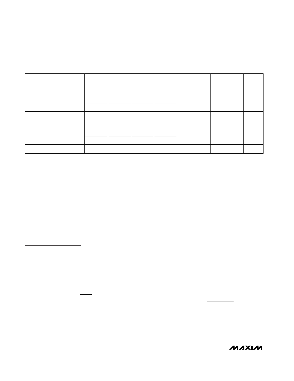
Table 2. Operating Mode Truth Table
OPERATING
MODE
TRACK
ONA
ONB
ONL
LINEAR
REGULATOR
DC-DC
CONVERTER
REF
Shutdown
X
L
H
L
OFF
OFF
OFF
H
H
X
X
Track
H
X
L
X
ON
ON
ON
L
H
X
H
Independent Regulation
L
X
L
H
ON
ON
ON
L
H
X
L
DC-DC Only
L
X
L
L
OFF
ON
ON
LDO Only
X
L
H
H
ON
OFF
ON
Dual Mode is a trademark of Maxim Integrated Products