Table 1. selecting the operating mode – Rainbow Electronics MAX1765 User Manual
Page 11
less power. SKIP mode allows higher efficiency than
PWM under light-load conditions.
Light-Load Operation in Normal Mode
At light loads, the MAX1765 operates by turning on the
DC-DC converter’s N-channel field-effect transistor
(FET) when V
FB
< V
REF
, synchronized with the rising
edge of the oscillator. The N-channel FET will remain
on, ramping up the inductor current past the minimum
inductor current, until the internal error amplifier and
current mode circuitry determine that the needs of the
system have been met or the device hits the ISET cur-
rent limit. The N-channel is then turned off and the P-
channel is turned on until current decays to the
P-channel turn-off current level. The N-channel will
remain off until V
FB
is again less than V
REF
, and a rising
edge of the oscillator occurs.
MAX1765
800mA, Low-Noise, Step-Up DC-DC Converter
with 500mA Linear Regulator
______________________________________________________________________________________
11
2.15V
ON
OUTL
POUT
LX
PGND
REF
SHUTDOWN
LOGIC
THERMAL
SENSOR
MAX1765
ERROR
AMP
STARTUP
OSCILLATOR
EN
Q
P
P
N
MOSFET DRIVER
WITH CURRENT
LIMITING
EN
1MHz
OSCILLATOR
EN
D
OSC
MODE
SKIP/PWM
Q
Q
IFB
PWM
CONTROLLER
RDY
1.250V
REFERENCE
IC PWR
IREF
ICS
FBL
OUT
V
OUT
ONL
INL
ONB
GND
ONA
V
OUT
- 300mV
ISET
ONL
REF
CLK/SEL
FB
TRACK
TRACK
ISET
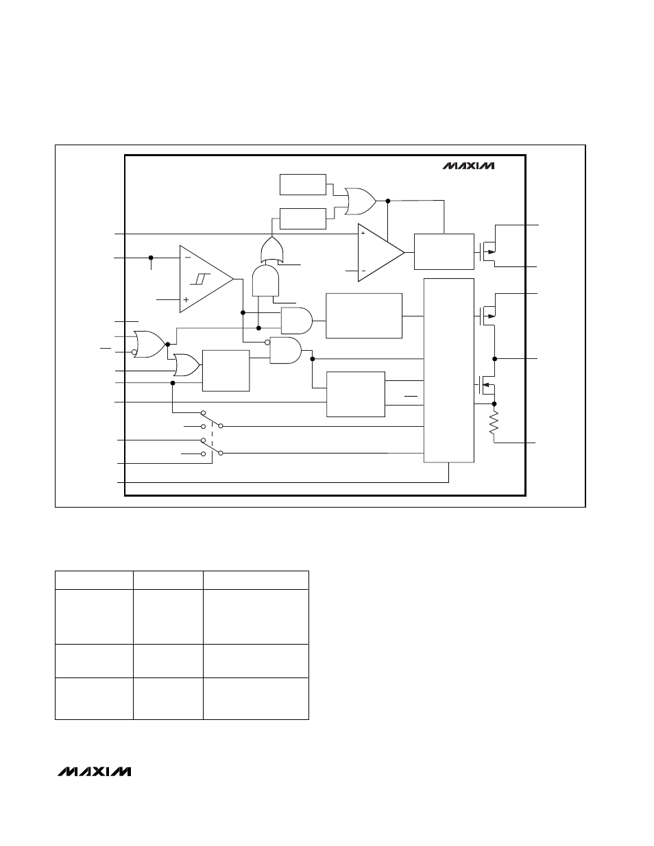
Figure 1. Functional Diagram
Table 1. Selecting the Operating Mode
CLK/SEL
MODE
FEATURES
0
Normal
Operation
High-efficiency pulse
skipping at light loads,
PWM at medium and
heavy loads
1
Forced PWM
Low noise, fixed
frequency at all loads
E xter nal C l ock
500kH z to
1.2M H z
Synchronized
PWM
Low noise, fixed
frequency at all loads