Pin description – Rainbow Electronics MAX2104 User Manual
Page 6
MAX2104
Direct-Conversion Tuner IC for
Digital DBS Applications
6
_______________________________________________________________________________________
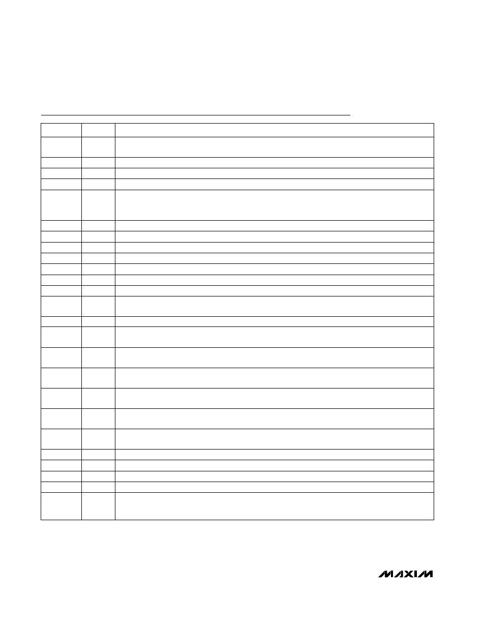
NAME
FUNCTION
PIN
Pin Description
2
CFLT
External Bypass for Internal Bias. Bypass this pin with a 0.1µF ceramic chip capacitor to GND.
3
XTL-
Inverting Input to Crystal Oscillator. Consult crystal manufacturer for circuit loading requirements.
4
XTL+
Noninverting Input to Crystal Oscillator. Consult crystal manufacturer for circuit loading requirements.
5, 9, 10,
15, 16, 32,
40, 41, 46
GND
Ground. Connect each of these pins to a solid ground plane. Use multiple vias to reduce inductance
where possible.
7
RFIN-
RF Inverting Input. Bypass RFIN- with 47pF capacitor in series with a 75
Ω resistor to GND.
8
RFIN+
RF Noninverting Input. Connect to 75
Ω source with a 47pF ceramic chip capacitor.
11
QDC-
Baseband Offset Correction. Connect a 0.22µF ceramic chip capacitor from QDC- to QDC+ (pin 12).
12
QDC+
Baseband Offset Correction. Connect a 0.22µF ceramic chip capacitor from QDC+ to QDC- (pin 11).
13
IDC-
Baseband Offset Correction. Connect a 0.22µF ceramic chip capacitor from IDC- to IDC+ (pin 14).
14
IDC+
Baseband Offset Correction. Connect a 0.22µF ceramic chip capacitor from IDC+ to IDC- (pin 13).
17
RFOUT
Buffered RF Output. Enabled when INSEL is low.
18
CPG1
Charge-Pump Gain Select. High-impedance digital input. Sets the charge-pump output scaling. See the
DC Electrical Characteristics section for available gain settings.
20
XTLOUT
Buffered Crystal Oscillator Output
21
CPG2
Charge-Pump Gain Select. High-impedance digital input. Sets the charge-pump output scaling. See the
DC Electrical Characteristics section for available gain settings.
22
GC1
Gain Control Input for RF Front End. High-impedance analog input, with an input range of 1V to 4V. See
the AC Electrical Characteristics section for transfer function.
23
GC2
Gain Control Input for Baseband Signals. High-impedance analog input, with an input range of 1V to 4V.
See the AC Electrical Characteristics section for transfer function.
24
INSEL
Loopthrough Mode Enable. High-impedance digital input. Drive low to enable the RFOUT buffer and
disable the internal downconverters. Connect to V
CC
for normal tuner operation.
25
FLCLK
Baseband Filter Cutoff Adjust. Connect to a slew-rate-limited clock source. See the AC Electrical
Characteristics section for transfer function.
26
FDOUB
LO Frequency Doubler. High-impedance digital input. Drive high to enable the LO frequency doubler.
Drive low to disable the doubling function.
27
QOUT-
Baseband Quadrature Output. Connect to inverting input of high-speed ADC.
28
QOUT+
Baseband Quadrature Output. Connect to noninverting input of high-speed ADC.
30
IOUT-
Baseband In-Phase Output. Connect to inverting input of high-speed ADC.
31
IOUT+
Baseband In-Phase Output. Connect to noninverting input of high-speed ADC.
33
MOD+
PECL Modulus Control. A PECL high on MOD+ sets the dual-modulus prescaler to divide by 32. A PECL
logic low sets the divide ratio to 33. Drive with a differential PECL signal with MOD- (pin 34).
1, 6, 19,
29, 39, 45
V
CC
V
CC
Power-Supply Input. Connect each pin to a +5V ±5% low-noise supply. Bypass each V
CC
pin to the
nearest GND with a ceramic chip capacitor.