Ac electrical characteristics (continued) – Rainbow Electronics MAX2104 User Manual
Page 5
MAX2104
Direct-Conversion Tuner IC for
Digital DBS Applications
_______________________________________________________________________________________
5
Note 1:
Minimum and maximum values are guaranteed by design and characterization over supply voltage.
Note 2:
With external 100
Ω termination resistor.
Note 3:
Driving differential load of 10k
Ω || 15pF.
Note 4:
Two signals are applied to RFIN_ at f
LO
- 100MHz and f
LO
- 199MHz. V
GC2
= 1V; V
GC1
is set such that the baseband out-
puts are at 590mV
P-P
. IM products are measured at baseband outputs but are referred to RF inputs.
Note 5:
Two signals are applied to RFIN_ at 1200MHz and 2150MHz. V
GC2
= 1V, V
GC1
is set such that the baseband outputs are
at 590mV
P-P
. IM products are measured at baseband outputs but are referred to RF inputs.
Note 6:
P
RFIN_
= -40dBm so that front end IM contributions are minimized.
Note 7:
Using L64733/L64734 demo board from LSI Logic.
Note 8:
Downconverted level, in dBc, of carrier present at f
LO
x 2, f
LO
= 1180MHz, f
VCO
= 590MHz, V
FDOUB
= 2.4V.
Note 9:
Downconverted level, in dBc, of carrier present at f
O
/ 2, f
LO
= 2175MHz, f
VCO
= 1087.5MHz, V
FDOUB
= 2.4V.
Note 10: Leakage is dominated by board parasitics.
Note 11: V
CPG1
= V
CPG2
= V
FDOUB
= V
INSEL
= 0.5V, f
FLCLK
= 0.5MHz.
Note 12: Measured at tuned frequency with PLL locked. All phase noise measurements assume tank components have a Q > 50.
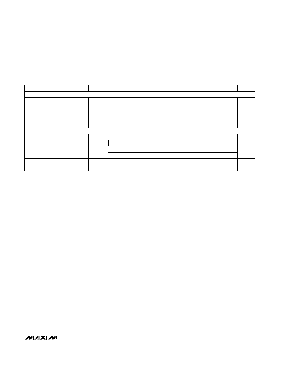
AC ELECTRICAL CHARACTERISTICS (continued)
(V
CC
= 4.75V to 5.25V, V
IOUT_
= V
QOUT_
= 0.59V
P-P
, C
IOUT_
= C
QOUT_
= 10pF, f
FLCLK
= 2MHz, R
IOUT_
= R
QOUT_
= 10k
Ω,
V
FDOUB
= V
INSEL
= V
CPG1
= V
CPG2
= 2.4V, V
PLLIN+
= V
MOD+
= 1.3V, V
PLLIN-
= V
MOD-
= 1.1V, T
A
= +25°C. Typical values are at
V
CC
= 5.0V and T
A
= +25°C, unless otherwise noted.)
LOCAL OSCILLATOR
SYNTHESIZER
-95
PARAMETER
SYMBOL
MIN
TYP
MAX
UNITS
At 100kHz offset, f
LO
= 2175MHz
dBc/Hz
LO Phase Noise (Notes 7, 12)
-75
At 10kHz offset, f
LO
= 2175MHz
57
0
Figure 1
f
RFIN_
= 2150MHz
dB
RFIN_ to LO Input Isolation
(Note 10)
-55
590
1180
MHz
LO Tuning Range (Note 1)
ns
4
7.26
MHz
Crystal Frequency Range (Note 1)
2
0.75
1
1.5
Load = 10pF | | 10k
Ω, f
XTLOUT
= 6MHz
V
P-P
XTLOUT Output Voltage Swing
V
XTLOUT Output Voltage DC
At 1kHz offset, f
LO
= 2175MHz
MOD+, MOD- Hold Time (Note 1)
t
HM
7
Figure 1
CONDITIONS
ns
MOD+, MOD- Setup Time (Note 1)
t
SUM
SYNTHESIZER
LOCAL OSCILLATOR