Max781 pda/hand-held computer power controller, Typical operating characteristics (continued), Pin description – Rainbow Electronics MAX781 User Manual
Page 7
MAX781
PDA/Hand-Held Computer Power Controller
_______________________________________________________________________________________
7
10
1
10
100
1000
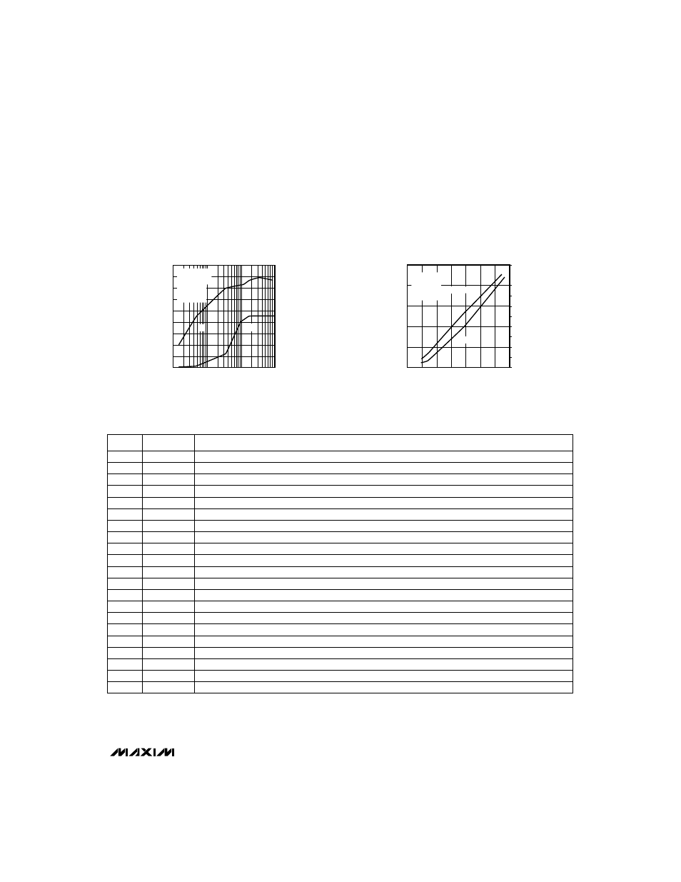
3OUT OPERATE MODE POWER EFFICIENCY
VARIABLE SWITCHING FREQUENCY
MAX781-09
3OUT OUTPUT CURRENT (mA)
POWER EFFICIENCY (%)
20
30
40
50
60
70
80
90
100
BATT = 7.5V
SYNC = AGND
IDLE = 1
MODE1 = 1
MODE0 = 0
0
50
100
150
200
250
300
350
400
450
SWITCHING EFFICIENCY (kHz)
%
kHz
0
0
USING THE BATTERY CHARGER TO DRIVE
A CCFL BACKLIGHT ROYER OSCILLATOR
MAX781-01
CHG6–CHG0 BITS VALUE
CCFL TUBE CURRENT (mA, rms)
CSBAT AVERAGE VOLTAGE (mV)
10
20
mV
30
40
50
60
70
80
90
100
110
10
20
30
40
50
60
70
0.5
1.0
1.5
2.0
2.5
SYNC = REF
VCHG = 7V
BATT = VCHG - DIODE DROP
R4 = 0.47
Ω
mA, rms
____________________________Typical Operating Characteristics (continued)
(T
A
= +25°C, unless otherwise noted.)
______________________________________________________________Pin Description
21
DLO
+3.3V Regulator, Synchronous Rectifier, Gate-Driver Output
22
BST
+3.3V Regulator Boost Capacitor Connection (0.1µF to LX)
23
DHI
+3.3V Regulator High-Side Gate-Driver Output
24
LX
+3.3V Regulator Inductor Connection
20
PGND
Power Ground
12
DOUT
Serial-Interface Data Output
13
DIN
Serial-Interface Data Input
16
COMP
Battery-Charger Compensation
NAME
FUNCTION
1–4
GD2–GD5
High-Side Gate-Driver Outputs
5
VPPA
VPP-Programming Voltage Output A
PIN
17
CSBAT
Battery-Charger Current-Sense Input
18
5OUT
Linear-Regulated +5V Output
19
DCHG
Battery-Charger MOSFET Gate-Driver Output
14
INT
Interrupt Output
15
FAST
General-purpose open-drain output
8
AGND
Analog Ground
9
SYNC
Oscillator Frequency Control and Synchronization Input
10
CE
Serial-Interface Chip-Enable Input—active high
11
SCLK
Serial-Interface Clock Input
6
VHI
VPPA, VPPB Linear-Regulator Input Power
7
VPPB
VPP-Programming Voltage Output B