Max781, Pda/hand-held computer power controller, Component selection and layout – Rainbow Electronics MAX781 User Manual
Page 16: Table 6. analog multiplexer channel selection
MAX781
_Component Selection and Layout
3.3V Output
Input and Output Bypass Capacitors
Capacitor C15 ensures that the buck regulator has a
low AC-impedance power source. C15’s root mean
square ripple-current rating must be greater than 0.5 x
(maximum power output capability of the system) /
3.3V. Capacitor C6 keeps 3OUT output ripple low and
stabilizes the regulation loop. C15 and C6 must have
low equivalent series resistance (ESR), preferably with
less than 0.2
Ω
of ESR at 200kHz. Tantalum capacitors
typically have the lowest ESR. C15’s ground connec-
tion must be as close as possible to C6’s ground con-
nection; ideally, the two capacitors will be grounded at
the same point. The MAX781’s AGND pin should only
connect to system ground at the ground connection of
C15 and C6. If the PC board has a ground plane, a
separate trace should directly connect AGND to the
ground connections of C15 and C6. Likewise, the
BATT pin should only connect to the battery at C15’s
positive terminal.
The capacitance and ESR of C6 determine loop stabili-
ty. To ensure loop stability, the minimum capacitance
and maximum ESR values are:
C6 > 2.5V / (3.3V x R7 x 2 x p x GBWP)
with C6 specified in Farads, R7 specified in ohms,
GBWP = gain bandwidth product of 60,000Hz, and:
C6 ESR < (3.3V x R7) / 2.5V
with C6 ESR specified in ohms, and R7 specified in
ohms.
In order to achieve the required low ESR, it may be
appropriate to select a value greater than the minimum
for C6, or to construct a composite C6 by paralleling
several smaller capacitors.
Current-Sense Resistor
Current-sense resistor R7 sets the maximum peak cur-
rent through power switch M1 and the primary of trans-
former T1. The MAX781’s maximum peak current limit
is 120mV / R, where R is the minimum possible resis-
tance for R7, and 120mV is the maximum electrical
specification for the current-limit threshold. For exam-
ple, selecting a 0.082
Ω
±1% resistor for R7 yields a
maximum peak current limit of 120mV / 0.082
Ω
x 0.99 =
1.478A. The maximum peak current limit must be less
than or equal to the maximum allowed continuous DC
current through either M1 or the primary of T1.
R7 also determines how much power 3OUT, VPPA, and
VPPB can deliver. The current-limit threshold can be
as small as 80mV and, using a 0.082
Ω
±1% resistor,
PDA/Hand-Held Computer Power Controller
16
______________________________________________________________________________________
1
0
0
1
1
0
0
1
MUX0
TEMP/1.5
BATT/5
VPPB/5.3
REF
AUXIN/1.5
AOUT
OUTPUTS
1
0
1
0
VPPA/5.3
0
1
0
1
5OUT/2.2
3OUT/1.5
0
MUX2
0
1
1
0
1
1
0
MUX1
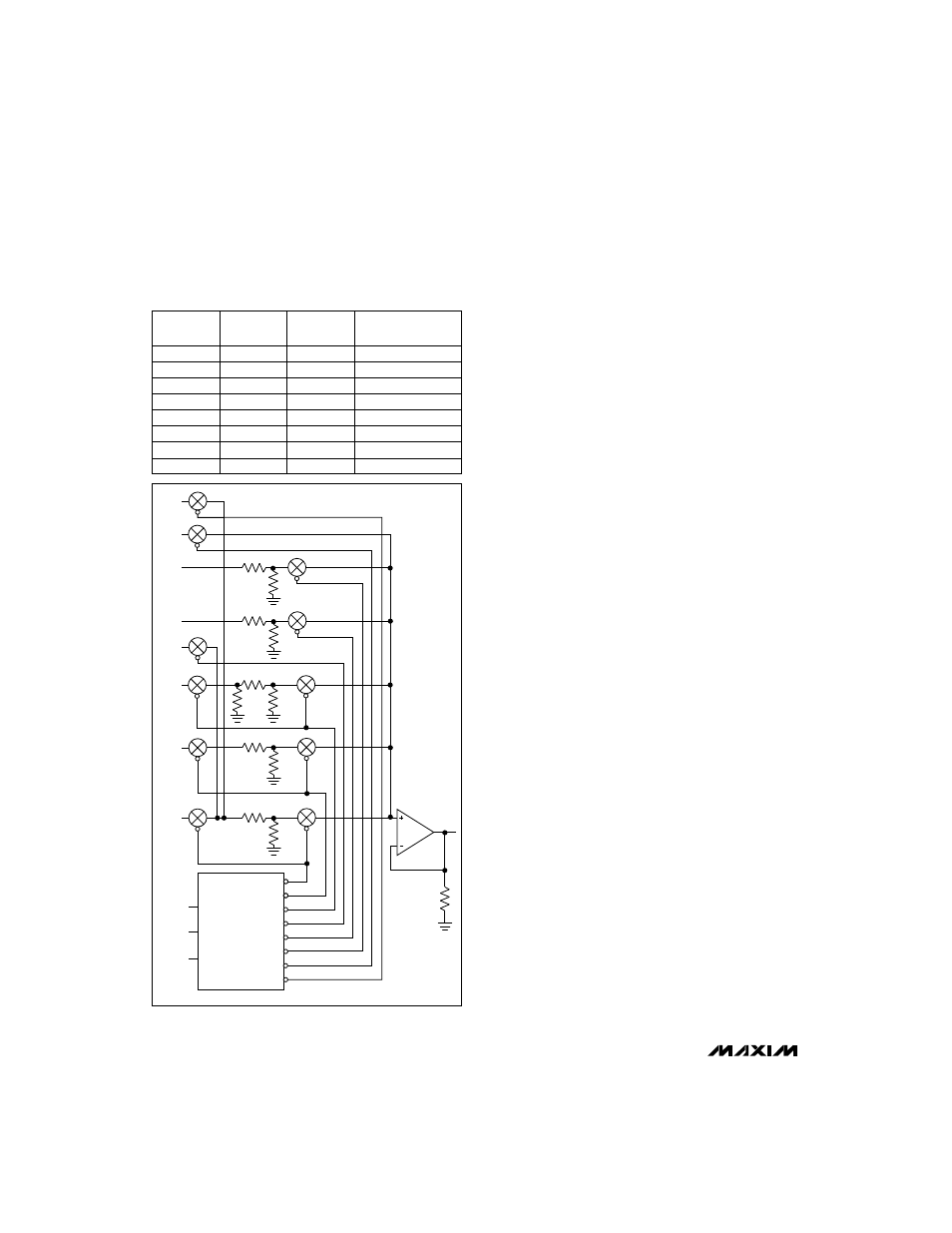
Table 6. Analog Multiplexer Channel Selection
500k
498.4k
116k
116k
125k
359k
183.3k
89.7k
300k
498.4k
200k
150k
AUXIN
REF
VPPB
VPPA
TEMP
BATT
5OUT
AOUT
3OUT
MUX0
MUX1
MUX2
3-to-8
DECODER
Y7
Y6
Y5
Y4
Y3
Y2
Y0
A0
A2
A1
Y1
Figure 9. Analog Multiplexer Circuitry