Max781 pda/hand-held computer power controller – Rainbow Electronics MAX781 User Manual
Page 2
MAX781
PDA/Hand-Held Computer Power Controller
2
_______________________________________________________________________________________
ABSOLUTE MAXIMUM RATINGS
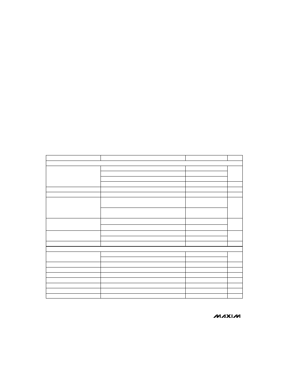
ELECTRICAL CHARACTERISTICS
(BATT = 6V, power-on reset state, T
A
= T
MIN
to T
MAX
, unless otherwise noted.)
Stresses beyond those listed under “Absolute Maximum Ratings” may cause permanent damage to the device. These are stress ratings only, and functional
operation of the device at these or any other conditions beyond those indicated in the operational sections of the specifications is not implied. Exposure to
absolute maximum rating conditions for extended periods may affect device reliability.
BATT, VCHG, VHI to AGND.........................................-0.3V, 20V
VPPA, VPPB to AGND..................................................-0.3V, 20V
FAST, GD1, GD2, GD3, GD4, GD5 to AGND ..............-0.3V, 20V
BST to AGND ...............................................................-0.3V, 30V
BST to LX .......................................................................-0.3V, 7V
DHI to LX .......................................................-0.3V, (BST + 0.3V)
PGND to AGND ........................................................-0.3V, +0.3V
All Other Pins to AGND or PGND ..................................-0.3V, 7V
VPPA, VPPB Current .........................................................100mA
5OUT Current....................................................................100mA
3OUT Current......................................................................40mA
Continuous Power Dissipation (T
A
= +70°C)
SSOP (derate 11.76mW/°C above +70°C) ....................941mW
Operating Temperature Ranges
MAX781CBX .........................................................0°C to +70°C
MAX781EBX ......................................................-40°C to +85°C
Storage Temperature Range .............................-65°C to +150°C
Lead Temperature (soldering, 10sec) .............................+300°C
Low-power mode,
–
S
—
H
—
D
—
N
–
= BATT = 18V
Shutdown mode,
–
S
—
H
—
D
—
N
–
= 0V
SYNC = AGND or 5OUT
SYNC = REF
Low-power mode, 5.5V < BATT < 18V,
0mA < I
5OUT
< 10mA
Operate or standby mode, 5.5V < BATT < 18V,
0mA < I
5OUT
< 25mA
Standby mode,
–
S
—
H
—
D
—
N
–
= BATT = 18V
Operate mode,
–
S
—
H
—
D
—
N
–
= BATT = 18V
No load
V
5OUT
falling
I
SOURCE
= -20µA to 100µA
V
5OUT
rising
CONDITIONS
nA
-100
100
SYNC Leakage Current
V
3.8
SYNC Input Voltage High
V
0.75
SYNC Input Voltage Low
µs
1
SYNC Rise Time (Note 1)
ns
200
SYNC Fall Time (Note 1)
ns
500
SYNC Minimum Pulse Width (Note1)
kHz
270
350
SYNC Capture Range (Note 1)
kHz
170
230
260
Internal Oscillator Frequency
270
300
340
nA
50
UVLO Input Bias Current
V
4.10
4.35
4.50
Internal Undervoltage Lockout
Threshold (measured at 5OUT,
UVLO = AGND)
4.30
4.60
4.80
60
120
10
V
4.8
5.2
5OUT Output Voltage
4.8
5.2
µA
250
750
mA
1
2
BATT Quiescent Supply Current
V
2.463
2.5
2.537
REF Output Voltage
mV
-20
20
REF Load Regulation
UNITS
MIN
TYP
MAX
PARAMETER
V
UVLO
falling
V
UVLO
rising
%REF
90
96
UVLO Threshold
(measured at UVLO)
97
103
SUPPLY AND REFERENCE
INTERNAL OSCILLATOR