Rainbow Electronics MAX534 User Manual
Page 12
MAX534
+5V, Low-Power, 8-Bit Quad DAC
with Rail-to-Rail Output Buffers
12
______________________________________________________________________________________
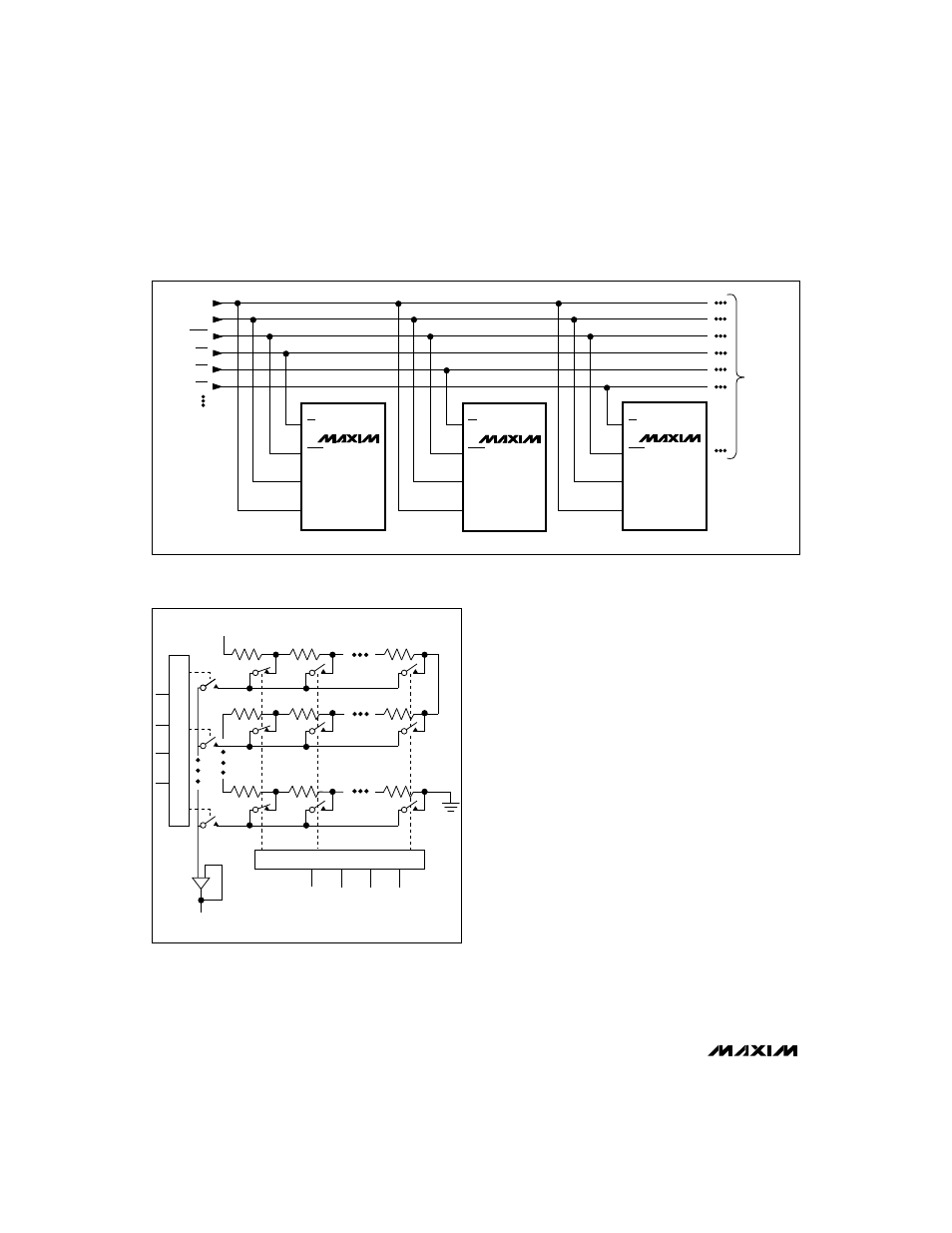
CS
LDAC
SCLK
DIN
MAX534
CS
LDAC
SCLK
DIN
MAX534
CS
LDAC
SCLK
DIN
MAX534
TO OTHER
SERIAL
DEVICES
DIN
SCLK
LDAC
CS1
CS2
CS3
Figure 7. Multiple MAX534s sharing one DIN line. Simultaneously update by strobing
LDAC, or specifically update by enabling an
individual
CS.
Output Buffer Amplifiers
All MAX534 voltage outputs are internally buffered by
precision unity-gain followers that slew at about
0.6V/µs. The outputs can swing from GND to V
DD
. With
a 0V to +4V (or +4V to 0V) output transition, the amplifi-
er outputs will typically settle to 1/2LSB in 8µs when
loaded with 10k
Ω
in parallel with 100pF.
The buffer amplifiers are stable with any combination of
resistive (
≥
10k
Ω
) or capacitive loads.
R1
R0
REF
D7
D5
D6
D4
R15
R16
R255
LSB DECODER
D2
D3
DAC A
D1
D0
MSB DECODER
Figure 8. DAC Simplified Circuit Diagram