Typical operating characteristics (continued), Pin description – Rainbow Electronics MAX1201 User Manual
Page 6
M
A
X12
01
+5V Single-Supply, 2.2Msps, 14-Bit
Self-Calibrating ADC
6
_______________________________________________________________________________________
-1.0
-0.5
0
0.5
1.0
-8192
-4096
0
-6144
2048
-2048
4096 6144 8192
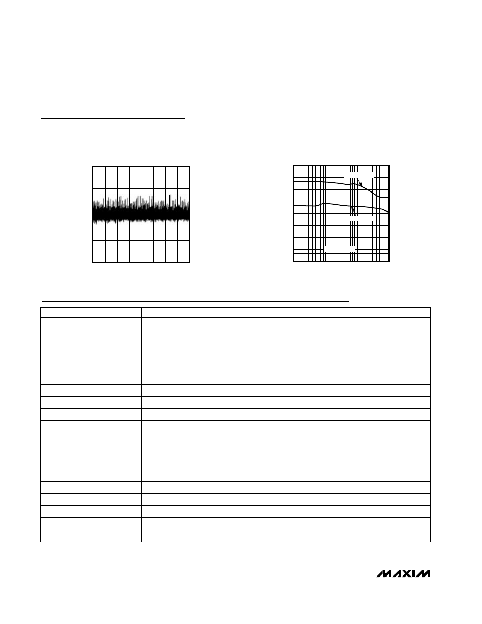
DIFFERENTIAL NONLINEARITY vs.
TWO’S COMPLEMENT OUTPUT CODE
MAX1201 toc9
TWO’S COMPLEMENT OUTPUT CODE
DNL (LSB)
14.0
13.5
13.0
10.0
1k
10k
100k
1M
EFFECTIVE NUMBER OF BITS
vs. INPUT FREQUENCY
MAX1201 toc10
INPUT FREQUENCY (Hz)
ENOB (BITS)
11.0
10.5
12.0
12.5
11.5
A
IN
= -0.5dBFS
A
IN
= -6dBFS
A
IN
= -20dBFS
Typical Operating Characteristics (continued)
(AV
DD
= +5V, DV
DD
= DRV
DD
= +3.3V, V
RFPS
= +4.096V, V
RFNS
= AGND, f
CLK
= 4.5056MHz, differential input, V
CM
= +2.048V, cal-
ibrated, T
A
= +25°C, unless otherwise noted.)
Pin Description
2, 4, 5
1
11
10
9
8
7
14
13
12
NAME
FUNCTION
AGND
Analog Ground
ST_CAL
Digital Input to Start Calibration.
ST_CAL = 0: Normal conversion mode.
ST_CAL = 1: Start self-calibration.
D10
Bit 10
D11
Bit 11
D12
Bit 12
D13
Bit 13 (MSB)
DOR
Data Out-of-Range Bit
D7
Bit 7
D8
Bit 8
D9
Bit 9
3, 6
AV
DD
Analog Power Supply, +5V ±5%
PIN
17, 28
16
15
20
19
18
DGND
Digital Ground
DRV
DD
Digital Power Supply for the Output Drivers. +3V to +5.25V, DRV
DD
≤
DV
DD
.
D6
Bit 6
D3
Bit 3
D4
Bit 4
D5
Bit 5