Detailed description – Rainbow Electronics MAX1801 User Manual
Page 7
MAX1801
Digital Camera Step-Up Slave
DC-DC Controller
_______________________________________________________________________________________
7
MAX1801
DL
FB
COMP
GND
IN
3.3V
1.25V
REF
OSC
DCON
FDN337N
MBRO520L
R1
R2
R3
R4
C
IN
10
µ
F
R
C
10k
V
BATT
V
OUT
C
C
1000pF
L
2.2
µ
H
MAX1800
OR
MAX1802
C
OUT
47
µ
F
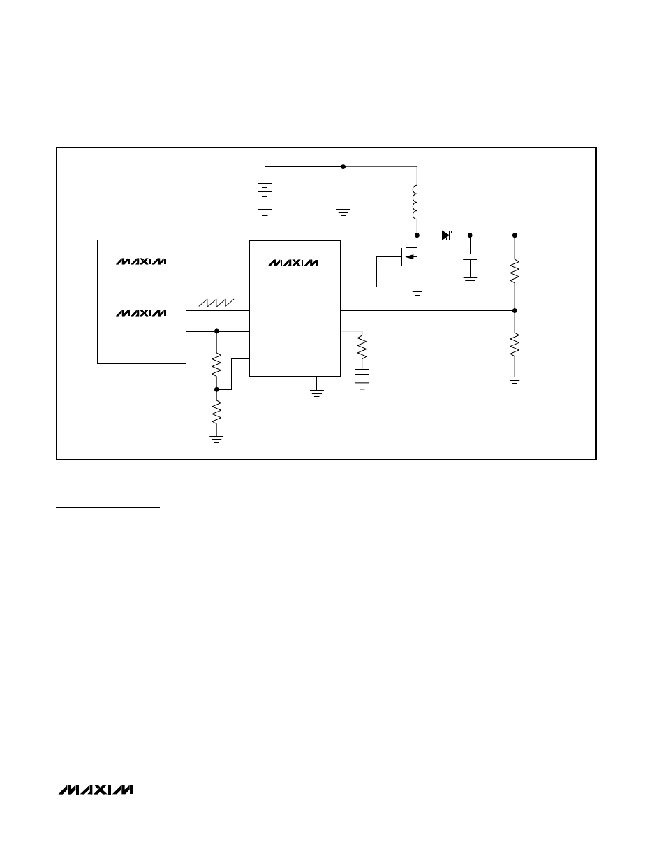
Figure 1. Typical Application Circuit
Detailed Description
Master-Slave Configuration
The MAX1801 is a step-up slave DC-DC controller that
obtains its input power, voltage reference, and oscilla-
tor signal directly from a MAX1800 or MAX1802 master
DC-DC converter (Figure 1). The master-slave configu-
ration reduces system cost by eliminating redundant
circuitry and controls the harmonic content of noise by
synchronizing converter switching.
Step-Up DC-DC Controller
The MAX1801 controller operates in a low-noise fixed-
frequency PWM mode, with output power limited by the
external components. The controller regulates the out-
put voltage by modulating the pulse width of the drive
signal for an external N-channel MOSFET switch. The
user-adjusted switching frequency is constant (100kHz
to 1MHz) and set by the master converter.
Figure 2 shows a block diagram of the MAX1801 PWM
controller. A sawtooth oscillator signal from the master
converter (at OSC) governs the internal timing. At the
beginning of each cycle, DL goes high to turn on the
external MOSFET switch. The MOSFET switch turns off
when the internally level-shifted sawtooth waveform
voltage rises above the voltage at COMP or when the
maximum duty cycle is exceeded. The switch remains
off until the beginning of the next cycle. An internal
transconductance amplifier establishes an integrated
error voltage at COMP, increasing the loop gain for
improved regulation accuracy and compensation con-
trol.
Reference
The MAX1801 requires a 1.25V reference voltage that
is obtained from the MAX1800 or the MAX1802. REF
typically sinks 0.5µA in shutdown mode, 3µA in active
mode, and up to 30µA during startup. If multiple
MAX1801 controllers are turned on simultaneously,
ensure that the master voltage reference can provide
sufficient current, or buffer the reference with an appro-
priate unity-gain amplifier.