Rainbow Electronics MAX1801 User Manual
Page 14
MAX1801
Digital Camera Step-Up Slave
DC-DC Controller
14
______________________________________________________________________________________
Using the MAX1801 Controller in
SEPIC Configuration
In cases where the battery voltage is above or below
the required output voltage, neither a step-up nor a
step-down converter is suitable; use a step-up/step-
down converter instead. One type of step-up/step-
down converter is the SEPIC shown in Figure 6.
Inductors L1 and L2 can be separate inductors or can
be wound on a single core and coupled as with a trans-
former. Typically, using a coupled inductor improves
efficiency because some power is transferred through
the coupling so that less power passes through the cou-
pling capacitor, C2. Likewise, C2 should be a low-ESR-
type capacitor to improve efficiency. The coupling
capacitor ripple current rating must be greater than the
larger of the input and output currents. The MOSFET
(Q1) drain-source voltage rating and the rectifier (D1)
reverse voltage rating must exceed the sum of the input
and output voltages. Other types of step-up/step-down
circuits are a flyback converter and a step-up converter
followed by a linear regulator.
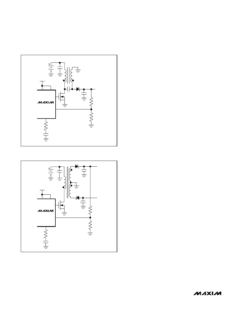
Using the MAX1801 Controller for a
Multi-Output Flyback Circuit
Some applications require multiple voltages from a sin-
gle converter that features a flyback transformer.
Figure 7 shows a MAX1801 auxiliary controller in a two-
output flyback configuration. The controller drives an
external MOSFET that switches the transformer primary,
and the two secondaries generate the outputs. Only a
single positive output voltage can be regulated using
the feedback resistive voltage-divider, so the other volt-
ages are set by the turns ratio of the transformer secon-
daries. The regulation of the other secondary voltages
degrades due to transformer leakage inductance and
winding resistance. Voltage regulation is best when the
load current is limited to a small range. Consult the
transformer manufacturer for the proper design for a
given application.
Using a Charge Pump to Make
Negative Output Voltages
Negative output voltages can be produced without a
transformer using a charge-pump circuit with an auxil-
iary controller, as shown in Figure 8. When MOSFET Q1
turns off, the voltage at its drain rises to supply current
to V
OUT
+. At the same time, C1 charges to the voltage
at V
OUT
+ through D1. When the MOSFET turns on, C1
discharges through D3, thereby charging C3 to V
OUT
-
minus the drop across D3, to create roughly the same
voltage as V
OUT
+ at V
OUT
- but with inverted polarity. If
different magnitudes are required for the positive and
negative voltages, a linear regulator can be used at one
of the outputs to achieve the desired voltages, while the
MAX1801 regulates the higher magnitude voltage.
MAX1801
D
1
L
2
C
2
R
1
OUTPUT
3.3V
R
2
R
C
G
C
Q
1
INPUT
1 CELL
Li+
MAIN
ON
COMP
DCON
EXT
FB
Figure 6. MAX1801 Auxiliary Controller, SEPIC Configuration
MAX1801
+ OUTPUT
- OUTPUT
D
3
D
2
R
1
R
2
R
C
G
C
Q
1
INPUT
MAIN
ON
COMP
DCON
EXT
FB
Figure 7. MAX1801 Auxiliary Controller, Flyback Configuration