Table 1. component suppliers, Selecting diodes, Selecting capacitors – Rainbow Electronics MAX686 User Manual
Page 12
MAX686
DAC-Controlled Boost/Inverter
LCD Bias Supply with Internal Switch
12
______________________________________________________________________________________
Selecting Diodes
The MAX686’s high switching frequency demands a
high-speed rectifier. Schottky diodes, such as the
1N5818 or MBR0530L, are recommended. Make sure
that the diode’s peak current rating exceeds the peak
current set by ISET and that its breakdown voltage
exceeds the output voltage. Schottky diodes are pre-
ferred due to their low forward voltage. However, ultra-
high-speed silicon rectifiers are also acceptable. Table 1
lists Schottky diode suppliers.
Selecting Capacitors
Output Filter Capacitors
The primary selection criterion for the output filter
capacitor is low equivalent series resistance (ESR). The
product of the peak inductor current and the output fil-
ter capacitor’s ESR determines the amplitude of the
high-frequency ripple seen on the output voltage.
These requirements can be balanced by appropriately
selecting the current limit, as discussed in the
Setting
the Peak Inductor Current Limit
section. Table 1 lists
some low-ESR capacitor suppliers.
Bypass Capacitors
Although the output current of many MAX686 applica-
tions may be relatively small, the input supply must be
able to source current transients equal to the ISET cur-
rent limit. The input bypass capacitor reduces the peak
currents drawn from the voltage source and reduces
noise caused by the MAX686’s switching action. The
input source impedance determines the size of the
capacitor required at the input (V
IN
). As with the output
filter capacitor, low ESR is the primary consideration. A
15µF, low-ESR capacitor is adequate for most applica-
tions, although smaller bypass capacitors may also be
acceptable in light-load applications. Bypass the IC
separately with a 0.1µF ceramic capacitor placed as
close as possible to the V
CC
and GND pins.
Bypass REF to GND with a 0.1µF ceramic capacitor for
REF currents up to 25µA. REF can source up to 50µA of
current for external loads. For 25µA
≤
I
REF
≤
50µA,
bypass REF with a 0.47µF capacitor.
Table 1. Component Suppliers
MAX686
V
CC
V
CC
= 2.7V
TO 5.5V
V
IN
= 0.8V
TO 27.5V
22
µ
H
MBR0530L
LX
DACOUT
15
µ
F
0.1
µ
F
FB
R3
C
F
V
OUT
R1
R2
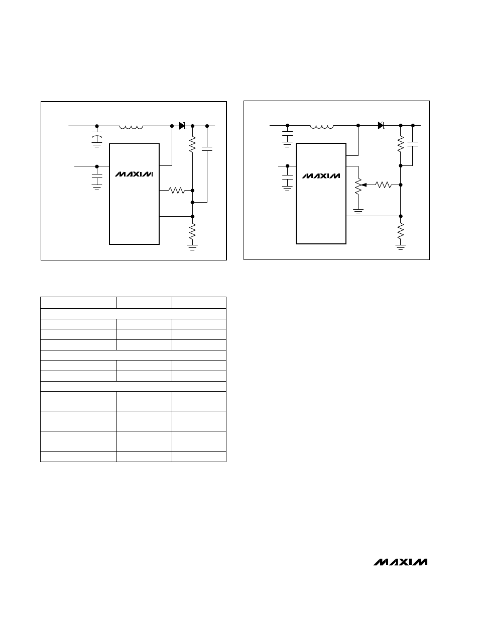
Figure 4. Feed-Forward Capacitor
Figure 5. Using a Potentiometer to Adjust Output Voltage
MAX686
V
CC
V
CC
= 2.7V
TO 5.5V
V
IN
= 0.8V
TO 27.5V
REF
LX
15
µ
F
22
µ
H
0.1
µ
F
FB
R3
C
F
V
OUT
R
POT
R1
100k
POTENTIOMETER
R2
MBR0530L
SUPPLIER
PHONE
FAX
(603) 224-1430
(603) 224-1961
Sprague 595D series
(847) 639-1469
Murata-Erie: LQH4
series
(814) 237-1431
(814) 238-0490
(847) 956-0702
(847) 390-4428
(847) 390-4373
(847) 956-0666
Sumida: CD43, CD54,
and CD74 series
TDK: NLC565050 series
Coilcraft: DO1608 and
DT1608 series
(847) 639-6400
(803) 626-3123
(803) 946-0690
AVX: TPS series
(714) 960-6492
(714) 969-2491
Matsuo: 267 series
(602) 994-6430
(602) 303-5454
Motorola: MBR0530L
(805) 867-2698
(805) 867-2555
Nihon; EC11 FS1 series
CAPACITORS
DIODES
INDUCTORS