Definitions – Rainbow Electronics MAX1031 User Manual
Page 20
MAX1027/MAX1029/MAX1031
Definitions
Integral Nonlinearity
Integral nonlinearity (INL) is the deviation of the values
on an actual transfer function from a straight line. This
straight line can be either a best-straight-line fit or a line
drawn between the end points of the transfer function,
once offset and gain errors have been nullified. INL for
the MAX1027/MAX1029/MAX1031 is measured using
the end-point method.
Differential Nonlinearity
Differential nonlinearity (DNL) is the difference between
an actual step width and the ideal value of 1 LSB. A
DNL error specification of less than 1 LSB guarantees
no missing codes and a monotonic transfer function.
Aperture Jitter
Aperture jitter (t
AJ
) is the sample-to-sample variation in
the time between the samples.
Aperture Delay
Aperture delay (t
AD
) is the time between the rising
edge of the sampling clock and the instant when an
actual sample is taken.
Signal-to-Noise Ratio
For a waveform perfectly reconstructed from digital
samples, signal-to-noise ratio (SNR) is the ratio of the
full-scale analog input (RMS value) to the RMS quanti-
zation error (residual error). The ideal, theoretical mini-
mum analog-to-digital noise is caused by quantization
error only and results directly from the ADC’s resolution
(N bits):
SNR = (6.02 x N + 1.76)dB
In reality, there are other noise sources besides quanti-
zation noise, including thermal noise, reference noise,
clock jitter, etc. Therefore, SNR is calculated by taking
the ratio of the RMS signal to the RMS noise, which
includes all spectral components minus the fundamen-
tal, the first five harmonics, and the DC offset.
Signal-to-Noise Plus Distortion
Signal-to-noise plus distortion (SINAD) is the ratio of the
fundamental input frequency’s RMS amplitude to the
RMS equivalent of all other ADC output signals:
SINAD (dB) = 20 x log (Signal
RMS
/ Noise
RMS
)
10-Bit 300ksps ADCs with FIFO,
Temp Sensor, Internal Reference
20
______________________________________________________________________________________
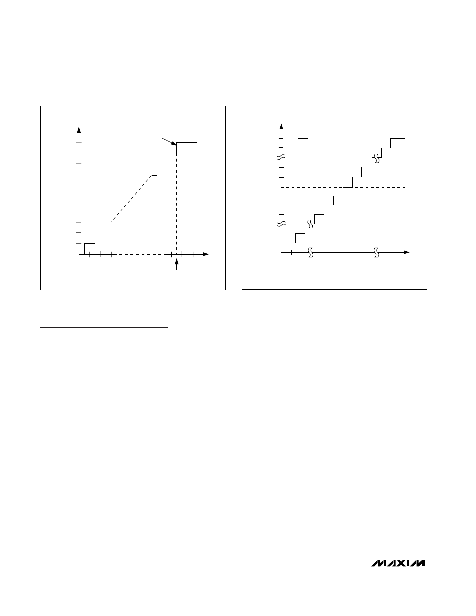
OUTPUT CODE
FULL-SCALE
TRANSITION
11 . . . 111
11 . . . 110
11 . . . 101
00 . . . 011
00 . . . 010
00 . . . 001
00 . . . 000
1
2
3
0
(COM)
FS
FS - 3/2 LSB
FS = V
REF
+ V
COM
ZS = V
COM
INPUT VOLTAGE (LSB)
1 LSB =
V
REF
1024
Figure 9. Bipolar Transfer Function, Full Scale (±FS) = ±V
REF
/ 2
011 . . . 111
011 . . . 110
000 . . . 010
000 . . . 001
000 . . . 000
111 . . . 111
111 . . . 110
111 . . . 101
100 . . . 001
100 . . . 000
- FS
COM*
INPUT VOLTAGE (LSB)
OUTPUT CODE
ZS = COM
+FS - 1 LSB
*V
COM
≥ V
REF
/ 2
+
V
COM
FS
=
V
REF
2
-FS =
-V
REF
2
1 LSB =
V
REF
1024
Figure 8. Unipolar Transfer Function, Full Scale (FS) = V
REF