Chip information – Rainbow Electronics MAX1089 User Manual
Page 14
MAX1086–MAX1089
150ksps, 10-Bit, 2-Channel Single-Ended, and
1-Channel True-Differential ADCs in SOT23
14
______________________________________________________________________________________
Aperture Definitions
Aperture jitter (t
AJ
) is the sample-to-sample variation in
the time between the samples. Aperture delay (t
AD
) is
the time between the rising edge of the sampling clock
and the instant when an actual sample is taken.
Signal-to-Noise Ratio
For a waveform perfectly reconstructed from digital sam-
ples, signal-to-noise ratio (SNR) is the ratio of full-scale
analog input (RMS value) to the RMS quantization error
(residual error). The ideal, theoretical minimum analog-to-
digital noise is caused by quantization error only and
results directly from the ADC’s resolution (N-bits):
SNR = (6.02
✕
N + 1.76)dB
In reality, there are other noise sources besides quanti-
zation noise: thermal noise, reference noise, clock jitter,
etc. SNR is computed by taking the ratio of the RMS
signal to the RMS noise, which includes all spectral
components minus the fundamental, the first five har-
monics, and the DC offset.
Signal-to-Noise Plus Distortion
Signal-to-noise plus distortion (SINAD) is the ratio of the
fundamental input frequency’s RMS amplitude to RMS
equivalent of all other ADC output signals.
SINAD (dB) = 20
✕
log (Signal
RMS
/ Noise
RMS
)
Effective Number of Bits
Effective number of bits (ENOB) indicates the global
accuracy of an ADC at a specific input frequency and
sampling rate. An ideal ADC’s error consists of quanti-
zation noise only. With an input range equal to the full-
scale range of the ADC, calculate the effective number
of bits as follows:
ENOB = (SINAD - 1.76) / 6.02
Total Harmonic Distortion
Total harmonic distortion (THD) is the ratio of the RMS
sum of the first five harmonics of the input signal to the
fundamental itself. This is expressed as:
where V
1
is the fundamental amplitude, and V
2
through
V
5
are the amplitudes of the 2nd- through 5th-order har-
monics.
Spurious-Free Dynamic Range
Spurious-free dynamic range (SFDR) is the ratio of RMS
amplitude of the fundamental (maximum signal compo-
nent) to the RMS value of the next largest distortion
component.
Chip Information
TRANSISTOR COUNT: 6922
PROCESS: BiCMOS
THD
V
V
V
V
V
=
×
+
+
+
20
2
2
3
2
4
2
5
2
1
log /
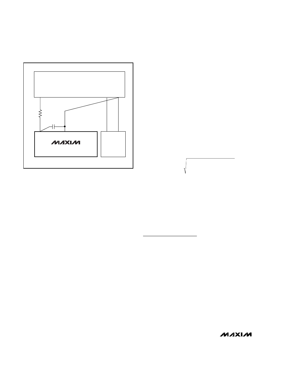
+3V OR +5V
V
LOGIC
= +5V/+3V GND
SUPPLIES
DGND
+5V/+3V
GND
0.1
µF
V
DD
DIGITAL
CIRCUITRY
MAX1086–
MAX1089
R* = 5
Ω
*OPTIONAL
Figure 11. Power-Supply and Grounding Connections