Typical operating characteristics, Electrical characteristics (continued) – Rainbow Electronics MAX1425 User Manual
Page 5
MAX1425
10-Bit, 20Msps ADC
_______________________________________________________________________________________
5
ELECTRICAL CHARACTERISTICS (continued)
Note 1:
Internal reference, REFIN bypassed to AGND with a 0.1µF capacitor.
Note 2:
External +2.5V reference applied to REFIN.
Note 3:
Internal reference disabled. V
REFIN
= 0, V
REFP
= 3.25V, V
CML
= 2.25V, and V
REFN
= 1.25V.
Note 4:
Measured as the ratio of the change in midscale offset voltage for a ±5% change in V
AVDD
using the internal reference.
Note 5:
IMD is measured with respect to either of the fundamental tones.
Note 6:
Specifies the common-mode range of the differential input signal supplied to the MAX1425.
Note 7:
Defined as the input frequency at which the fundamental component of the output spectrum is attenuated by 3dB.
Note 8:
V
REFIN
is internally biased to +2.5V through a 5k
Ω resistor.
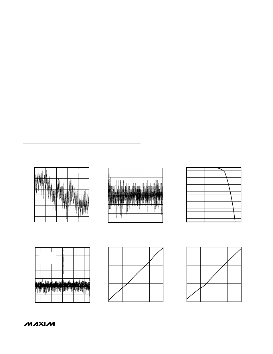
Typical Operating Characteristics
(V
AVDD
= V
CMLP
= +5V, V
DVDD
= +3.3V, V
CMLN
= V
AGND
= 0, internal reference, digital output load = 35pF, f
CLK
= 20Msps (50%
duty cycle), for dynamic performance 0dB is full scale, T
A
= +25°C, unless otherwise noted.)
-1.2
-0.6
-0.8
-1.0
-0.4
-0.2
0
0.2
0.4
0.6
0.8
0
400
200
600
800
1000
INTEGRAL NONLINEARITY vs. CODE
MAX1425-01
CODE
INL (LSB)
f
INP
= 2MHz
-0.6
-0.2
-0.4
0
0.2
0.4
0.6
0
400
200
600
800
1000
DIFFERENTIAL NONLINEARITY vs. CODE
MAX1425-02
CODE
DNL (LSB)
f
INP
= 2MHz
-8.0
-6.0
-7.0
-5.0
-4.0
-3.0
-2.0
-1.0
0
0.01
1
0.1
10
100
1000 10,000
ANALOG INPUT BANDWIDTH
(FULL POWER)
MAX1425-03
BANDWIDTH (MHz)
AMPLITUDE (dB)
-140
-100
-120
-60
-80
-20
-40
0
0
4
2
6
8
1
5
3
7
9
10
INTERMODULATION DISTORTION
vs. FREQUENCY
MAX1425-04
FREQUENCY (MHz)
MAGNITUDE (dB)
f
CLK
= 20MHz
f1 = 5.01MHz
f2 = 5.03MHz
f
CLK
= 20MHz
f1 = 5.01MHz
f2 = 5.03MHz
0
20
40
60
SIGNAL-TO-NOISE PLUS DISTORTION
vs. POWER (f
IN
= 2.003MHz)
MAX1425-05
INPUT (dB)
SINAD (dB)
-60
-30
-45
-15
0
0
20
40
60
SIGNAL-TO-NOISE RATIO PLUS DISTORTION
vs. POWER (f
IN
= 5.009MHz)
MAX1425-06
INPUT (dB)
SNDR (dB)
-60
-30
-45
-15
0