Connection diagram, Ordering information, Pin descriptions – Rainbow Electronics LM99 User Manual
Page 2
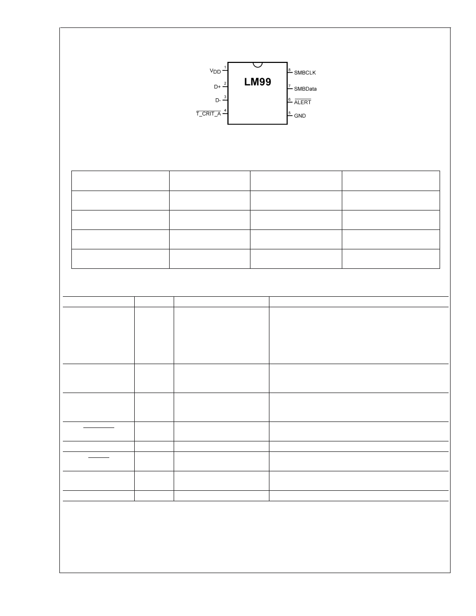
Connection Diagram
MSOP-8
20053802
TOP VIEW
Ordering Information
Part Number
Package
Marking
NS Package
Number
Transport
Media
LM99CIMM
T17C
MUA08A
(MSOP-8)
1000 Units on
Tape and Reel
LM99-1CIMM
T20C
MUA08A
(MSOP-8)
1000 Units on
Tape and Reel
LM99CIMMX
T17C
MUA08A
(MSOP-8)
3500 Units on
Tape and Reel
LM99-1CIMMX
T20C
MUA08A
(MSOP-8)
3500 Units on
Tape and Reel
Pin Descriptions
Label
Pin #
Function
Typical Connection
V
DD
1
Positive Supply Voltage Input
DC Voltage from 3.0 V to 3.6 V. V
DD
should be bypassed
with a 0.1 µF capacitor in parallel with 100 pF to ground.
The 100 pF capacitor should be placed as close as
possible to the power supply pin. A bulk capacitance of
approximately 10 µF needs to be in the vicinity of the LM99
V
DD
.
D+
2
Diode Current Source
To Diode Anode. Connected to the collector and base of
the remote discrete diode-connected transistor. Connect a
2.2 nF capacitor between pins 2 and 3.
D−
3
Diode Return Current Sink
To Diode Cathode. Connects to the emitter of the remote
diode-connected transistor. Connect a 2.2 nF capacitor
between pins 2 and 3.
T_CRIT_A
4
T_CRIT Alarm Output,
Open-Drain, Active-Low
Pull-Up Resistor, Controller Interrupt or Power Supply
Shutdown Control
GND
5
Power Supply Ground
Ground
ALERT
6
Interrupt Output, Open-Drain,
Active-Low
Pull-Up Resistor, Controller Interrupt or Alert Line
SMBData
7
SMBus Bi-Directional Data
Line, Open-Drain Output
From and to Controller, Pull-Up Resistor
SMBCLK
8
SMBus Input
From Controller, Pull-Up Resistor
LM99
www.national.com
2