11 digital filter, Figure 8. filter output response to a step input, 0 functional description – Rainbow Electronics LM99 User Manual
Page 13
1.0 Functional Description
(Continued)
1.11 DIGITAL FILTER
D2
D1
Filter
0
0
No Filter
0
1
Level 1
1
0
Level 1
1
1
Level 2
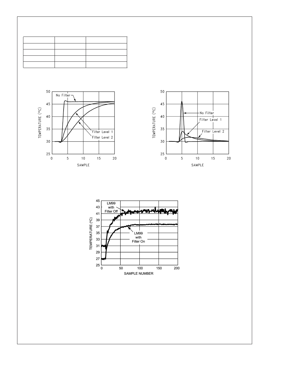
In order to suppress erroneous remote temperature readings
due to noise, the LM99 incorporates a user-configured digital
filter. The filter is accessed in the FILTER and ALERT CON-
FIGURE REGISTER at BFh. The filter can be set according
to the table shown.
Level 2 sets maximum filtering.
Figure 8 depict the filter output to in response to a step input
and an impulse input. Figure 9 depicts the digital filter in use
in a Pentium 4 processor system. Note that the two curves,
with filter and without, have been purposely offset so that
both responses can be clearly seen. Inserting the filter does
not induce an offset as shown.
20053825
a) Step Response
20053826
b) Impulse Response
FIGURE 8. Filter Output Response to a Step Input
20053827
FIGURE 9. Digital Filter Response in a Pentium 4 processor System. The filter on and off curves were purposely
offset to better show noise performance.
LM99
www.national.com
13