1 smbus timing diagrams, Figure 7. smbus timing diagrams, 10 serial interface reset – Rainbow Electronics LM99 User Manual
Page 12: 0 functional description, Lm99
1.0 Functional Description
(Continued)
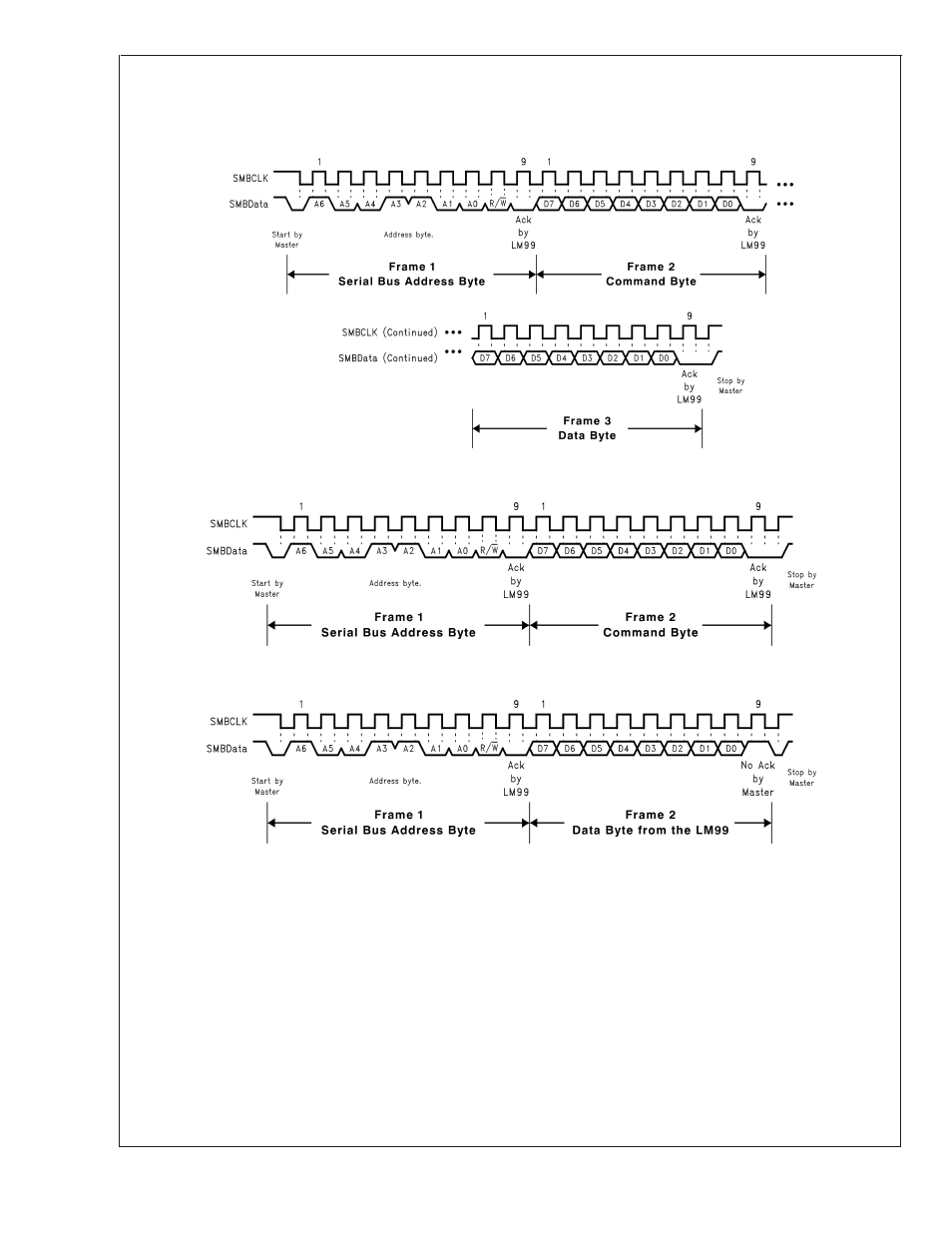
1.9.1 SMBus Timing Diagrams
LM99 Timing Diagram
1.10 SERIAL INTERFACE RESET
In the event that the SMBus Master is RESET while the
LM99 is transmitting on the SMBData line, the LM99 must be
returned to a known state in the communication protocol.
This may be done in one of two ways:
1.
When SMBData is LOW, the LM99 SMBus state ma-
chine resets to the SMBus idle state if either SMBData
or SMBCLK are held low for more than 35 ms (t
TIM-
EOUT
). Note that according to SMBus specification 2.0 all
devices are to timeout when either the SMBCLK or
SMBData lines are held low for 25-35 ms. Therefore, to
insure a timeout of all devices on the bus the SMBCLK
or SMBData lines must be held low for at least 35 ms.
2.
When SMBData is HIGH, have the master initiate an
SMBus start. The LM99 will respond properly to an
SMBus start condition at any point during the communi-
cation. After the start the LM99 will expect an SMBus
Address address byte.
20053810
(a) Serial Bus Write to the internal Command Register followed by a the Data Byte
20053811
(b) Serial Bus Write to the Internal Command Register
20053812
(c) Serial Bus Read from a Register with the Internal Command Register preset to desired value.
FIGURE 7. SMBus Timing Diagrams
LM99
www.national.com
12