3 status register (sr), 0 lm99 registers – Rainbow Electronics LM99 User Manual
Page 15
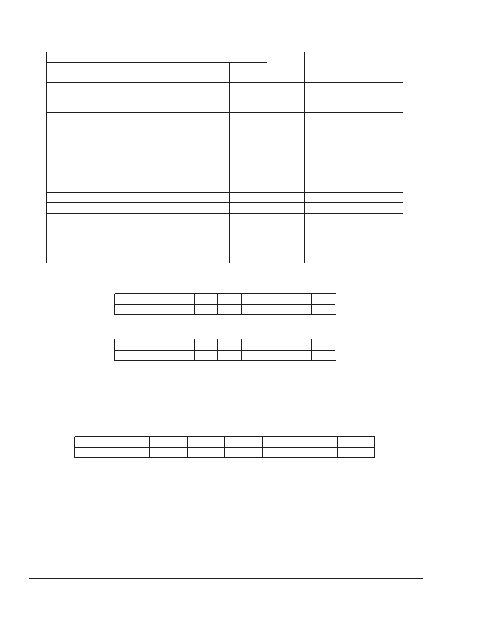
2.0 LM99 Registers
(Continued)
Command Select Address
Power On Default State
Register
Name
Register Function
Read Address
<
P7:P0
>
hex
Write Address
<
P7:P0
>
hex
<
D7:D0
>
binary
<
D7:D0
>
decimal
10h
NA
0000 0000
0
RTLB
Remote Temperature Low Byte
11h
11h
0000 0000
0
RTOHB
Remote Temperature Offset
High Byte
12h
12h
0000 0000
0
RTOLB
Remote Temperature Offset
Low Byte
13h
13h
0000 0000
0
RHSLB
Remote HIGH Setpoint Low
Byte
14h
14h
0000 0000
0
RLSLB
Remote LOW Setpoint Low
Byte
19h
19h
0110 1110
110
RCS
Remote T_CRIT Setpoint
20h
20h
0101 0101
85
LCS
Local T_CRIT Setpoint
21h
21h
0000 1010
10
TH
T_CRIT Hysteresis
B0h-BEh
B0h-BEh
Manufacturers Test Registers
BFh
BFh
0000 0000
0
RDTF
Remote Diode Temperature
Filter
FEh
NA
0000 0001
1
RMID
Read Manufacturer’s ID
FFh
NA
LM99 0011 0001
LM99-1 0011 0100
49
52
RDR
Read Stepping or Die Revision
Code
2.2 LOCAL and REMOTE TEMPERATURE REGISTERS (LT, RTHB, RTLB)
(Read Only Address 00h, 01h):
BIT
D7
D6
D5
D4
D3
D2
D1
D0
Value
SIGN
64
32
16
8
4
2
1
For LT and RTHB D7–D0: Temperature Data. LSB = 1˚C. Two’s complement format.
(Read Only Address 10h):
BIT
D7
D6
D5
D4
D3
D2
D1
D0
Value
0.5
0.25
0.125
0
0
0
0
0
For RTLB D7–D5: Temperature Data. LSB = 0.125˚C. Two’s complement format.
The maximum value available from the Local Temperature register is 127; the minimum value available from the Local
Temperature register is -128. The maximum value available from the Remote Temperature register is 127.875; the minimum value
available from the Remote Temperature registers is −128.875.
Note that the remote diode junction temperature is actually 16˚C higher than the Remote Temperature Register value.
2.3 STATUS REGISTER (SR)
(Read Only Address 02h):
D7
D6
D5
D4
D3
D2
D1
D0
Busy
LHIGH
LLOW
RHIGH
RLOW
OPEN
RCRIT
LCRIT
Power up default is with all bits “0” (zero).
D0: LCRIT: When set to “1” indicates a Local Critical Temperature alarm.
D1: RCRIT: When set to “1” indicates a Remote Diode Critical Temperature alarm.
D2: OPEN: When set to “1” indicates a Remote Diode disconnect.
D3: RLOW: When set to “1” indicates a Remote Diode LOW Temperature alarm
D4: RHIGH: When set to “1” indicates a Remote Diode HIGH Temperature alarm.
D5: LLOW: When set to “1” indicates a Local LOW Temperature alarm.
D6: LHIGH: When set to “1” indicates a Local HIGH Temperature alarm.
D7: Busy: When set to “1” ADC is busy converting.
LM99
www.national.com
15