Applications information, 5v, t, 25°c) – Rainbow Electronics MAX2684 User Manual
Page 15
MAX2683/MAX2684
3.5GHz Downconverter Mixers
with Selectable LO Doubler
______________________________________________________________________________________
15
as well as an output matching network for optimum per-
formance. See Typical Operating Circuit for recommend-
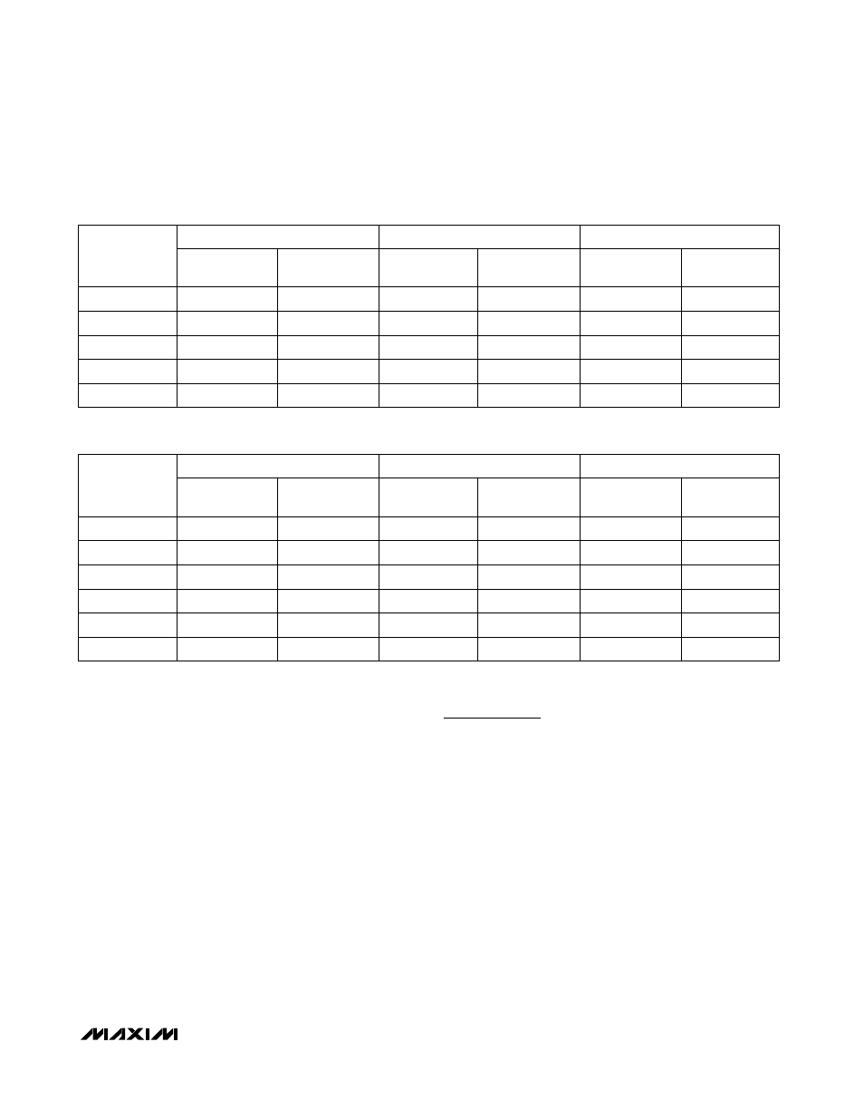
ed component values. See Tables 4 and 5 for IFOUT
port S-parameters.
Bias Circuitry
The linearity and supply current of the MAX2683/
MAX2684 are externally programmable with a single
resistor, R
BIAS
, from BIAS to GND. A nominal resistor
value of 1.2k
Ω will set an IIP3 of +9dBm and a supply
current of 55mA. Decreasing the resistor value
improves linearity at the cost of increased supply cur-
rent. Increasing the resistor value decreases supply
current while degrading linearity. Use resistor values in
the range of 820k
Ω to 2kΩ.
___________Applications Information
Layout Considerations
A properly designed PC board is an essential part of
any RF/microwave circuit. Keep RF signal lines as short
as possible to reduce losses, radiation, and induc-
tance. Use separate, low-inductance vias to the ground
plane for each ground pin. For best performance, sol-
der the exposed pad on the bottom of the device pack-
age evenly to the board ground plane.
Power-Supply and
ENX2
Bypassing
Proper voltage-supply bypassing is essential for high-
frequency circuit stability. Bypass V
CC
with a 10µF
capacitor in parallel with a 100pF capacitor located as
close to the V
CC
pin as possible.
Bypass ENX2 with a 100pF capacitor to ground to mini-
mize noise injected into the LO doubler cell. Use a
series resistor (typically 1.2k
Ω) to further reduce cou-
pling of high-frequency signals into the ENX2 pin.
R
BIAS
= 1.2k
Ω
S11 PHASE
(degrees)
-10.9
-23.5
-20.3
-17.2
-14.2
R
BIAS
= 1.2k
Ω
S11 MAG
S11 PHASE
(degrees)
S11 MAG
0.914
-11.2
0.930
0.893
-24.5
0.907
0.900
-21.3
0.911
0.905
-17.8
0.917
0.905
-14.7
0.920
R
BIAS
= 820
Ω
RF
FREQUENCY
(MHz)
S11 MAG
S11 PHASE
(degrees)
150
0.915
-11.3
350
0.894
-24.5
300
0.899
-21.3
250
0.904
-17.7
200
0.907
-14.8
R
BIAS
= 1.2k
Ω
S11 PHASE
(degrees)
-49.7
-53.3
-52.3
-51.4
-50.6
960
R
BIAS
= 1.2k
Ω
S11 MAG
S11 PHASE
(degrees)
S11 MAG
0.955
-49.6
0.955
0.940
-53.1
0.937
0.944
-52.3
0.941
0.948
-51.4
0.946
0.952
-50.5
0.950
R
BIAS
= 820
Ω
RF
FREQUENCY
(MHz)
S11 MAG
S11 PHASE
(degrees)
860
0.955
-49.4
940
0.943
-53.0
920
0.946
-52.0
900
0.950
-51.1
880
0.952
-50.3
0.941
-53.6
0.936
-54.0
0.935
-53.8
Table 5. MAX2684 IFOUT Port S-Parameters (V
CC
= +5V, T
A
= +25°C)
Table 4. MAX2683 IFOUT Port S-Parameters (V
CC
= +5V, T
A
= +25°C)