Pin description, Typical operating characteristics (continued), Max2684 – Rainbow Electronics MAX2684 User Manual
Page 11
MAX2683/MAX2684
3.5GHz Downconverter Mixers
with Selectable LO Doubler
______________________________________________________________________________________
11
Pin Description
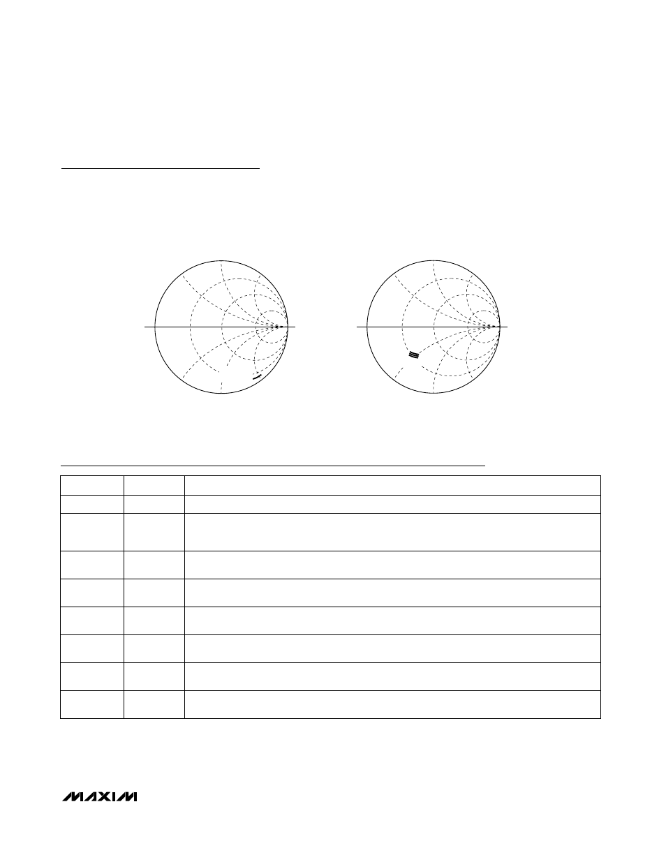
IF PORT S11 vs. R
BIAS
1.2k
Ω,
2k
Ω, 820kΩ
MAX2684
NAME
FUNCTION
1
V
CC
Supply Voltage Input. Bypass with a 100pF capacitor as close to the pin as possible.
2, 3, 5, 9,
10, 12, 13,
15, EP
GND
Ground. Connect to ground plane with a low-inductance connection. Solder exposed paddle
evenly to the board ground plane.
PIN
4
RFIN
RF Input Port to Mixer. Requires a matching network and a DC-blocking capacitor that may be part
of this network.
6
ENX2
LO Frequency-Doubler Enable Input. Drive low to enable the LO doubler and run external LO at
half frequency. Drive high to disable the LO doubler and run external LO at full frequency.
16
BIAS
Bias-Setting Resistor Connection. A resistor, R
BIAS
, placed from BIAS to GND sets the linearity and
supply current of the mixer.
11, 14
IFOUT-,
IFOUT+
Differential, Open-Collector IF Output Ports of Mixer. Requires a matching network and pull-up
inductors to V
CC
that can be part of this network.
8
LOX1
Full-Frequency Local-Oscillator Input to Downconverter Mixer. Requires a DC-blocking capacitor.
Leave unconnected if this pin is not used.
7
LOX2
Half-Frequency Local-Oscillator Input to LO Frequency Doubler, LO Filter, and Downconverter
Mixer. Requires a DC-blocking capacitor. Leave unconnected if this pin is not used.
RFIN S11 vs. R
BIAS
2k
Ω,
1.2k
Ω, 820kΩ
Typical Operating Characteristics (continued)
(MAX2683/MAX2684 EV kit, V
CC
= +5V, R
BIAS
= 1.2k
Ω, ENX2 = GND, f
RF
= 3.6GHz, P
RF
= -20dBm, f
LOX2
= 1650MHz for MAX2683 or
f
LOX2
= 1350MHz for MAX2684, P
LO
= -5dBm, all input/output ports terminated in 50
Ω, IFOUT+ and IFOUT- matched to single-ended
50
Ω load, T
A
= +25°C, unless otherwise noted.)