Static parameter definitions – Rainbow Electronics MAX1418 User Manual
Page 17
MAX1418
15-Bit, 65Msps ADC with -78.2dBFS
Noise Floor for IF Applications
______________________________________________________________________________________
17
Grounding
The practice of providing a split ground plane in an
attempt to confine digital ground return currents has
often been recommended in ADC application literature.
However, for converters such as the MAX1418, it is
strongly recommended to employ a single, uninterrupt-
ed ground plane. The MAX1427 EV kit achieves excel-
lent dynamic performance with such a ground plane.
The EP of the MAX1418 should be soldered directly to
a ground pad on layer 1 with vias to the ground plane
on layer 2. This provides excellent electrical and ther-
mal connections to the printed circuit.
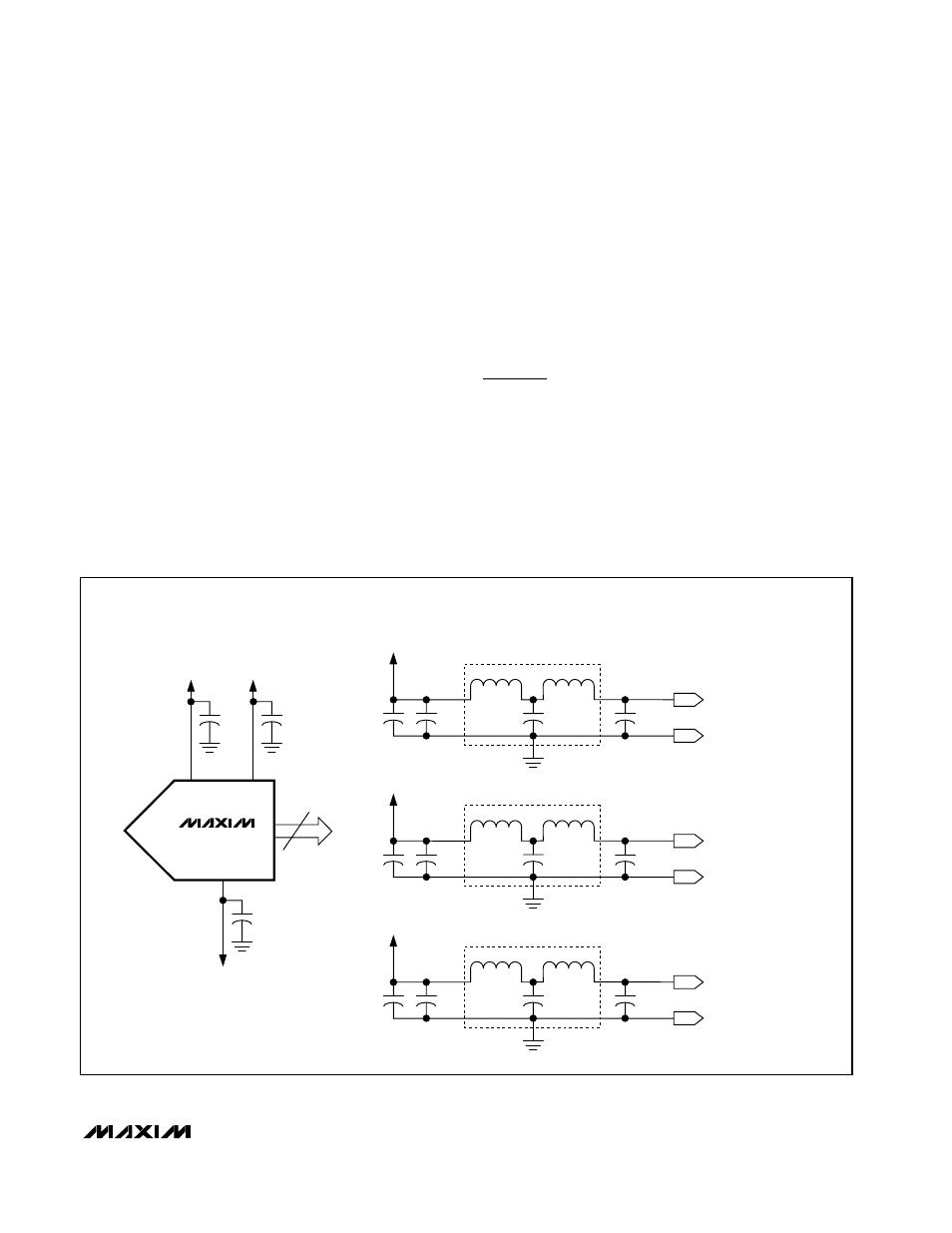
Supply Bypassing
The MAX1427 EV kit uses 220µF capacitors on each
supply line (AV
CC
, DV
CC
, and DRV
CC
) to provide low-
frequency bypassing. The loss (series resistance)
associated with these capacitors is actually of some
benefit in eliminating high-Q supply resonances. Ferrite
beads are also used on each of the supply lines to
enhance supply bypassing (Figure 9).
Small value (0.01µF to 0.1µF) surface-mount capacitors
should be placed at each supply pin or each grouping
of supply pins to attenuate high-frequency supply noise
(Figure 9). It is recommended to place these capacitors
on the topside of the board and as close to the device
as possible with short connections to the ground plane.
Static Parameter Definitions
Integral Nonlinearity (INL)
Integral nonlinearity is the deviation of the values on an
actual transfer function from a straight line. This straight
line can be either a best straight-line fit or a line drawn
between the end points of the transfer function, once
offset and gain errors have been nullified. However, the
static linearity parameters for the MAX1418 are mea-
sured using the histogram method with an input fre-
quency of 15MHz.
MAX1418
15
D0–D14
AV
CC
DV
CC
BYPASSING—ADC LEVEL
BYPASSING—BOARD LEVEL
0.1µF
DRV
CC
GND
0.1µF
GND
0.1µF
GND
10µF
47µF
220µF
AV
CC
FERRITE BEAD
10µF
47µF
220µF
DV
CC
FERRITE BEAD
10µF
47µF
220µF
DRV
CC
FERRITE BEAD
ANALOG
POWER-SUPPLY SOURCE
DIGITAL
POWER-SUPPLY SOURCE
OUTPUT-DRIVER
POWER-SUPPLY SOURCE
Figure 9. Grounding, Bypassing, and Decoupling Recommendations for MAX1418