Rainbow Electronics MAX495 User Manual
Page 13
The MAX492/MAX494/MAX495 can drive capacitive
loads in excess of 1000pF under certain conditions
(Figure 5). When driving capacitive loads, the greatest
potential for instability occurs when the op amp is
sourcing approximately 100µA. Even in this case, sta-
bility is maintained with up to 400pF of output capaci-
tance. If the output sources either more or less current,
stability is increased. These devices perform well with a
1000pF pure capacitive load (Figure 6). Figure 7 shows
the performance with a 500pF load in parallel with vari-
ous load resistors.
To increase stability while driving large capacitive
loads, connect a pull-up resistor at the output to
decrease the current that the amplifier must source. If
the amplifier is made to sink current rather than source,
stability is further increased.
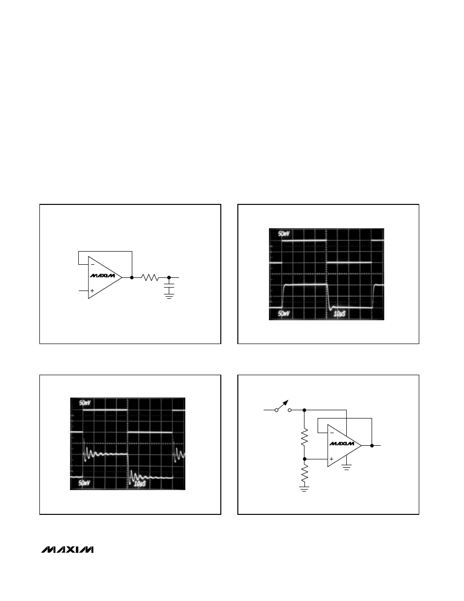
Frequency stability can be improved by adding an out-
put isolation resistor (R
S
) to the voltage-follower circuit
(Figure 8). This resistor improves the phase margin of
the circuit by isolating the load capacitor from the op
amp’s output. Figure 9a shows the MAX492 driving
10,000pF (R
L
≥
100k
Ω
), while Figure 9b adds a 47
Ω
isolation resistor.
MAX492/MAX494/MAX495
Single/Dual/Quad, Micropower,
Single-Supply Rail-to-Rail Op Amps
______________________________________________________________________________________
13
V
IN
50mV/div
V
OUT
50mV/div
10
µ
s/div
V
IN
50mV/div
V
OUT
50mV/div
10
µ
s/div
MAX495
V
OUT
V
CC
2
3
1k
1k
+5V
7
4
6
MAX49_
V
OUT
V
IN
C
L
R
S
Figure 10. Power-Up Test Configuration
Figure 9b. Driving a 10,000pF Capacitive Load with a 47
Ω
Isolation Resistor
Figure 9a. Driving a 10,000pF Capacitive Load
Figure 8. Capacitive-Load Driving Circuit