Max1747 triple charge-pump tft lcd dc-dc converter, Table 1. component suppliers – Rainbow Electronics MAX1747 User Manual
Page 12
MAX1747
Triple Charge-Pump TFT LCD
DC-DC Converter
12
______________________________________________________________________________________
Efficiency
≅ V
POS
/ [V
SUPP
✕
(N+1)] for the
positive low-power charge pump
where N is the number of charge-pump stages.
Output Voltage Selection
Adjust the main output voltage by connecting a volt-
age-divider from the output (V
OUT
) to FB and GND (see
Typical Operating Circuit). Adjust the negative low-
power output voltage by connecting a voltage-divider
from the output (V
NEG
) to FBN to REF. Adjust the posi-
tive low-power output voltage by connecting a voltage-
divider from the output (V
POS
) to FBP to GND. Select
R2, R4, and R6 in the 10k
Ω to 200kΩ range. Calculate
the remaining resistors with the following equations:
R1 = R2 [(V
OUT
/ V
REF
) – 1]
R3 = R4 [(V
POS
/ V
REF
) – 1]
R5 = R6 |V
NEG
/ V
REF
|
where V
REF
= 1.25V. V
OUT
may range from 4.5V to
5.5V, V
POS
may range from V
SUPP
to +35V, and V
NEG
may range from 0 to -35V.
Flying Capacitors
Increasing the flying capacitor’s value increases the
output-current capability. Above a certain point, larger
capacitor values lower the secondary pole formed by
the transfer capacitor and switch R
ON
, which destabi-
lizes the output. For the main charge pump, use a
ceramic capacitor based on the following equation:
For the low-power charge pumps, a 0.1µF ceramic
capacitor works well in most applications. Smaller val-
ues may be used for lower current applications.
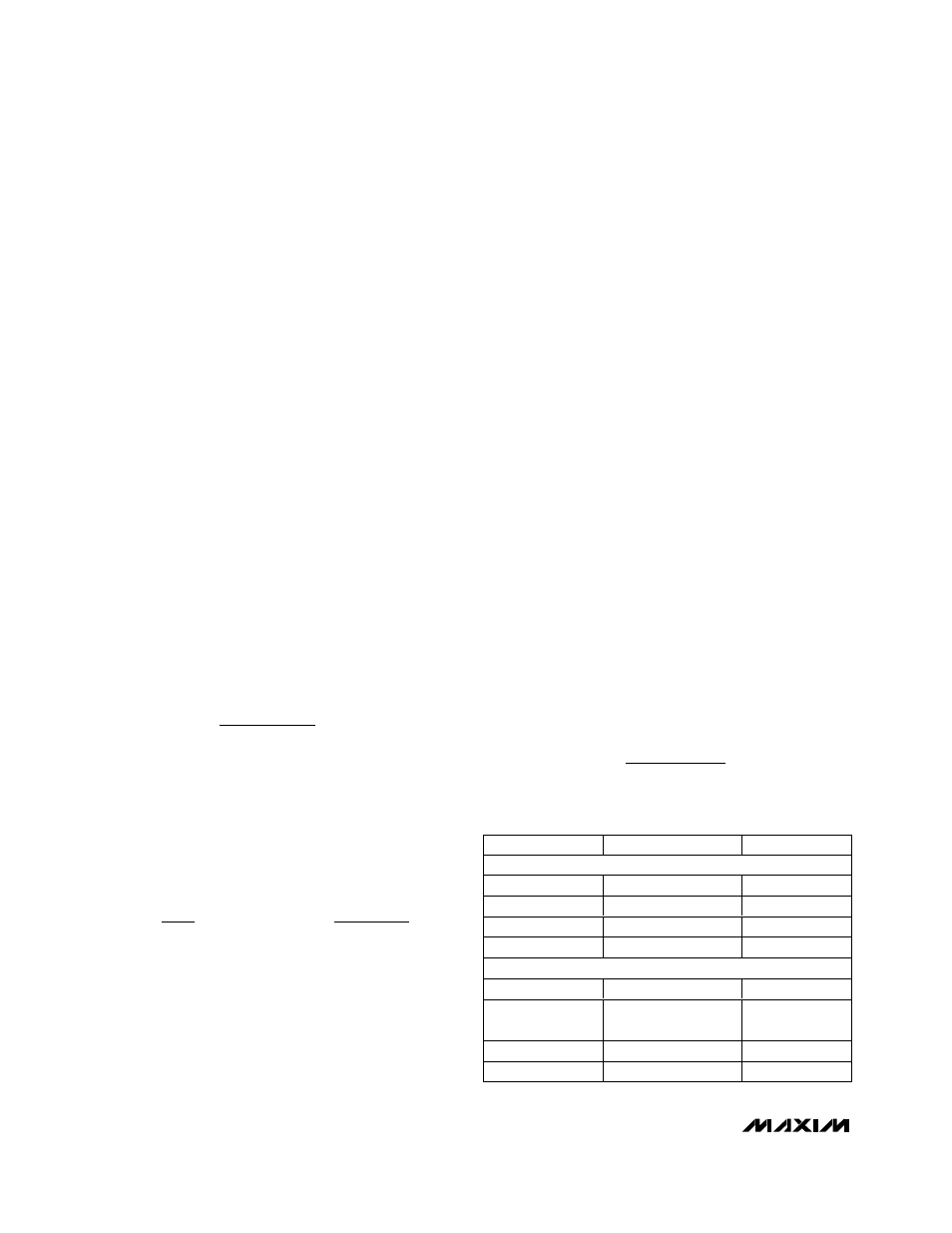
Component suppliers are listed in Table 1.
Output Capacitors
For the main charge pump, use a ceramic capacitor
based on the following equation:
For low-frequency applications (close to 200kHz),
selection of the output capacitor is limited solely by the
switching frequency. However, for high-frequency
applications (close to 2MHz), selection of the output
capacitor is limited by the secondary pole formed by
the flying capacitor and switch on-resistance.
For the low-power charge pumps, the output capacitor
should be anywhere from 5-times to 20-times larger
than the flying capacitor, depending on the ripple toler-
ance. Increasing the output capacitance or decreasing
the ESR reduces the output ripple voltage and the
peak-to-peak transient voltage.
Input Capacitors
Using an input capacitor with a value equal to or
greater than the output capacitor is recommended.
Place the capacitor as close to the IC as possible. If the
source impedance or inductance of the input supply is
large, additional input bypassing may be required.
For the low-power charge-pump inputs (SUPN and
SUPP), using bypass capacitors with values equal to or
greater than the flying capacitors is recommended.
Place these capacitors as close to the supply voltage
inputs as possible.
Rectifier Diodes
Use Schottky diodes with a current rating greater than
4 times the average output current, and with a voltage
rating of 1.5 times V
SUPP
for the positive charge pump
and V
SUPN
for the negative charge pump.
Integrator Capacitor
The MAX1747 contains an internal current integrator
that improves the DC load regulation but increases the
peak-to-peak transient voltage (see Load-Transient
Waveform in the Typical Operating Characteristics).
Connect a ceramic capacitor between INTG and GND
based on the following equation:
C
Hz
C
f
INTG
OUT
OSC
≥
×
150
C
M
C
M
OUT
X
≥
Ч
Ч
Ч
20
2
Hz
f
AND
F
Hz
f
OSC
OSC
µ
C
F
MHz
f
X
OSC
≤
µ ×
0 47
.
SUPPLIER
PHONE
FAX
CAPACITORS
AVX
803-946-0690
803-626-3123
Kemet
408-986-0424
408-986-1442
Sanyo
619-661-6835
619-661-1055
Taiyo Yuden
408-573-4150
408-573-4159
DIODES
Central
516-435-1110
516-435-1824
International
Rectifier
310-322-3331
310-322-3332
Motorola
602-303-5454
602-994-6430
Nihon
847-843-7500
847-843-2798
Table 1. Component Suppliers