Pin description (continued) – Rainbow Electronics MAX100 User Manual
Page 8
MAX100
250Msps, 8-Bit ADC with Track/Hold
8
_______________________________________________________________________________________
_________________________________________________Pin Description (continued)
72, 73
AIN+
75, 76
AIN-
Analog Inputs, internally terminated with 50
Ω
to ground. Full-scale linear input range is approximately
±270mV. Drive AIN+ and AIN- differentially for best high-frequency performance.
54
VA
RBS
Negative Reference Voltage Sense (Note 11)
55
VA
RB
Negative Reference Voltage Input (Note 11)
65
TP3
Internal node. Do not connect.
66
TP2
Internal node. Do not connect.
68
TP1
Internal connection. This pin
must
be connected to GND.
52
VA
CTS
Reference Bias Resistor Center-Tap Sense (Note 12)
53
VA
CT
Reference Bias Resistor Center Tap (Note 12)
NAME
FUNCTION
PIN
Note 10:
Use a multilayer board with a separate layer dedicated to ground. Connect GND and DGND in separate areas in the
ground plane (separated by at least 1/4 inch) and at only one location on the board (see
Typical Operating Circuit
).
Note 11:
Reference bias supply. Use a separate high-quality supply for these pins. Carefully bypassing these pins to achieve
noise-free operation of the reference supplies contributes directly to high ADC accuracy.
Note 12:
The center-tap connection of the MAX100 is normally left open. It can be driven with a bias voltage, but should be
bypassed carefully (refer to Note 11).
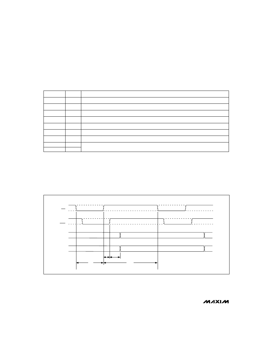
CLK
AData
BData
CLK
DCLK
DCLK
tpd1
tpd2
tpwh
tpwl
Figure 1. Output Timing: Divide-by-1 Mode (DIV = 0)