Table 2. output mode control – Rainbow Electronics MAX100 User Manual
Page 12
MAX100
250Msps, 8-Bit ADC with Track/Hold
12
______________________________________________________________________________________
Table 2. Output Mode Control
0
X
0
0
X
1
MOD
A=B
DIV
250
250
DCLK*
(MHz)
Data appears on
AData only, BData
port inactive
(Figure 3).
AData identical to
BData (Figure 3).
DESCRIPTION
125
1
0
0
8:16 demultiplexer
mode. AData
and BData ports
are active. BData
carries older
sample and
AData carries
most recent sam-
ple (Figure 4).
125
1
0
1
AData and BData
ports are active,
both carry identi-
cal sampled data.
Alternate samples
are taken but dis-
carded.
50
1
1
0
AData port
updates data on
5th input CLK.
BData port inac-
tive. Other 4 sam-
pled data points
are discarded.
50
1
1
1
AData and BData
ports are both
active with identi-
cal data. Data is
updated on out-
put ports every
5th input clock
(CLK). The other
4 samples are
discarded.
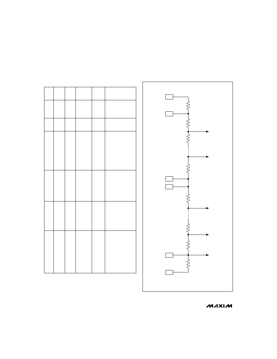
R
R
R
R
PARASITIC
RESISTANCE
TO
COMPARATORS
POSITIVE
REFERENCE
CENTER TAP
NEGATIVE
REFERENCE
R/2
R/2
VA
CTS
VA
CT
VA
RBS
VA
RB
VA
RT
VA
RTS
PARASITIC
RESISTANCE
Figure 6. Reference Ladder String
*Input clocks (CLK,
–
C
—
L
—
K
–
) = 250MHz for all above combinations.
In divide-by-2 or divide-by-5 mode the output clock DCLK will
always be a 50% duty-cycle signal. In divide-by-1 mode DCLK
will have the same duty cycle as CLK.
Divide
by 1
Divide
by 1
MODE
Divide
by 2
Divide
by 2
Divide
by 5
Divide
by 5