Typical operating characteristics, Timing characteristics – Rainbow Electronics MAX100 User Manual
Page 4
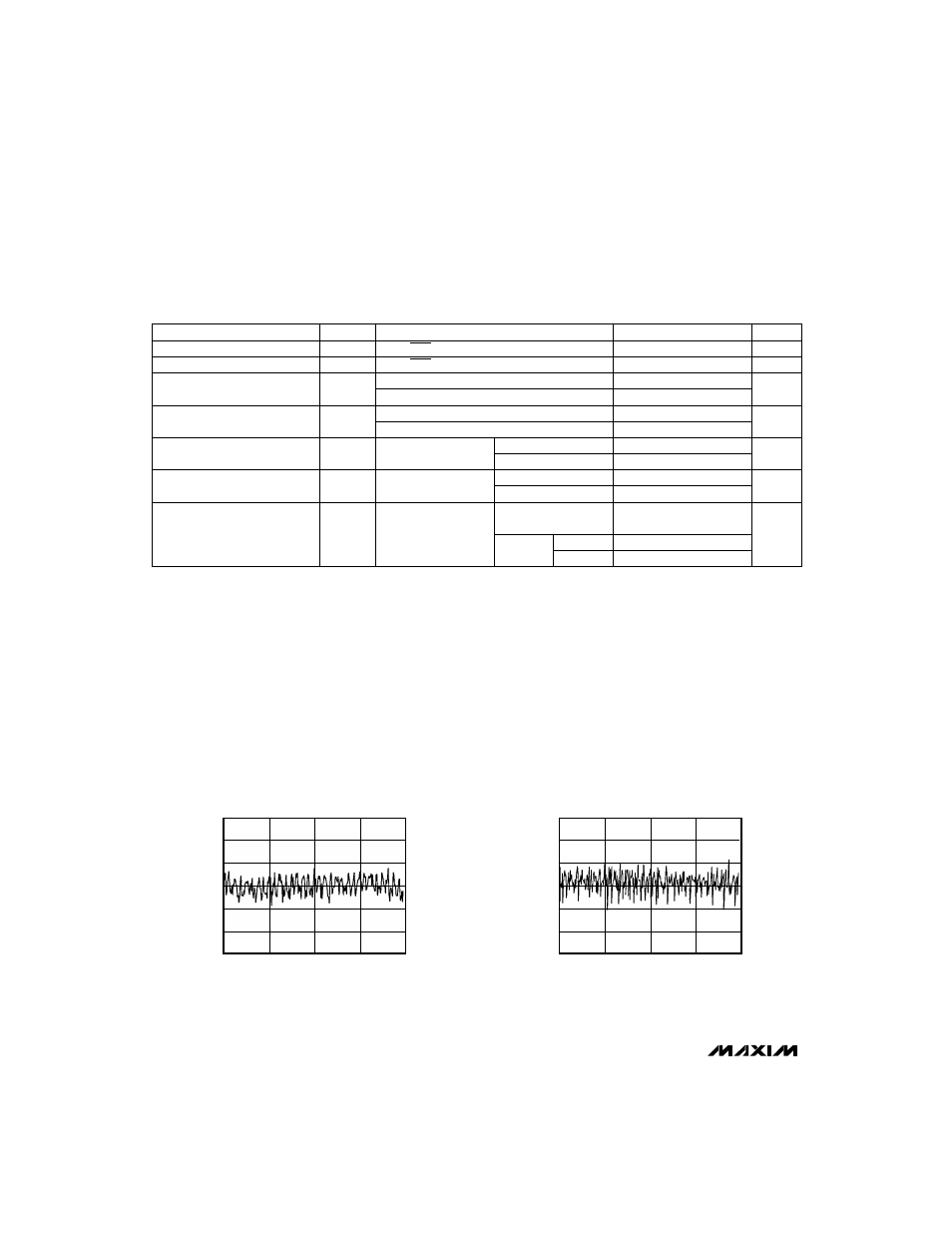
OUTPUT CODE
INTEGRAL NONLINEARITY
vs. OUTPUT CODE
0.75
0.50
0.25
0
-0.25
0
64
128
192
256
-0.50
-0.75
INL (LSBs)
OUTPUT CODE
DIFFERENTIAL NONLINEARITY
vs. OUTPUT CODE
0.75
0.50
0.25
0
-0.25
0
DNL (LSBs)
64
128
192
256
-0.50
-0.75
__________________________________________Typical Operating Characteristics
(T
A
= +25°C, unless otherwise noted.)
MAX100
250Msps, 8-Bit ADC with Track/Hold
4
_______________________________________________________________________________________
TIMING CHARACTERISTICS
(V
EE
= -5.2V, V
CC
= +5V, R
L
= 50
Ω
to -2V, VA
RT
= 1.02V, VA
RB
= -1.02V, T
A
= +25°C, unless otherwise noted.)
DIV = 0, Figure 1
DIV = 1, Figure 2
CLK, CLK, Figures 1 and 2
0.8
2.4
CLK, CLK, Figures 1 and 2
ns
1.9
5.7
t
PD1
CLK to DCLK
Propagation Delay
CONDITIONS
See Figures 3 and 4
and Table 1 (delay
depends on output
mode)
20% to 80%
Clock
Cycles
8 1/2
8 1/2
t
NPD
7 1/2
7 1/2
Pipeline Delay
(Latency)
7 1/2
7 1/2
ps
700
t
R
500
Rise Time
ns
1.9
t
PWH
ns
1.9
5.0
t
PWL
Clock Pulse Width Low
Clock Pulse Width High
UNITS
MIN
TYP
MAX
SYMBOL
PARAMETER
DIV = 0, Figure 1
DIV = 1, Figure 2
0.5
2.2
ns
-1.4
-0.1
t
PD2
DCLK to A/BData
Propagation Delay
DCLK
DATA
DCLK
DATA
20% to 80%
ps
550
t
F
600
Fall Time
Divide-by-1 mode
Divide-by-
2 mode
BData
AData
Note 3:
All devices are 100% production tested at +25°C and are guaranteed by design for T
A
= T
MIN
to T
MAX
as specified.
Note 4:
Deviation from best-fit straight line. See
Integral Nonlinearity
section.
Note 5:
See the
Signal-to-Noise Ratio and Effective Bits
section in the
Definitions of Specifications.
Note 6:
SNR calculated from effective bits performance using the following equation: SNR (dB) = 1.76 + (6.02) (effective bits).
Note 7:
Clock pulse width minimum requirements t
PWL
and t
PWH
must be observed to achieve stated performance.
Note 8:
Functionality guaranteed for -1.07
≤
V
IH
≤
-0.7 and -2.0
≤
V
IL
≤
-1.5.
Note 9:
Outputs terminated through 50
Ω
to -2.0V.