Pin description – Rainbow Electronics MAX100 User Manual
Page 7
MAX100
250Msps, 8-Bit ADC with Track/Hold
_______________________________________________________________________________________
7
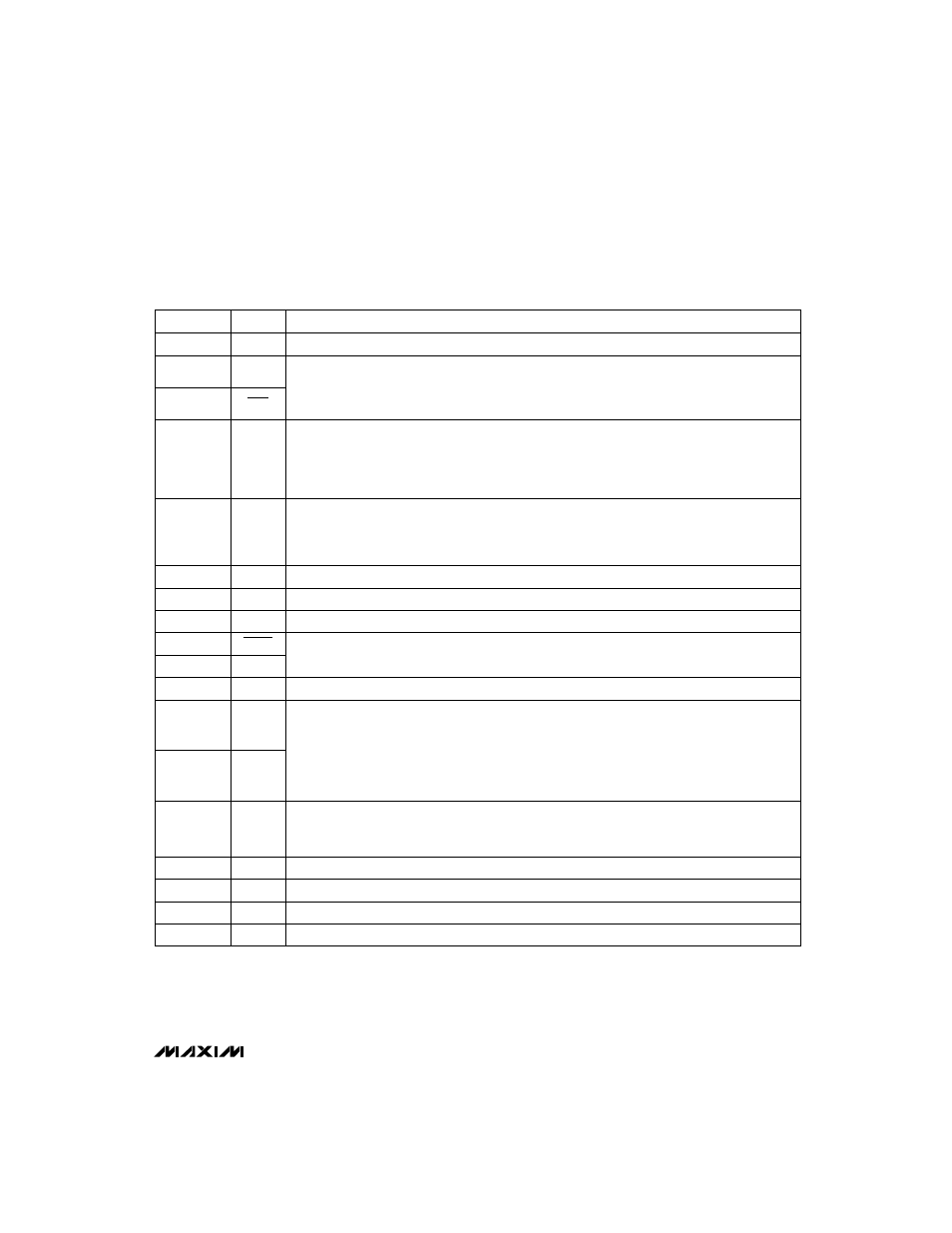
______________________________________________________________Pin Description
12
MOD
Modulus. MOD and DIV select the output modes. See Table 1.
5, 6, 9, 10,
31, 33, 35,
48, 58, 59,
63, 81, 83
N.C.
No Connect—there is no internal connection to these pins.
8, 21, 43, 56
VCC
Positive power supply, +5V ±5% nominal
13
DCLK
Complementary Differential Clock Outputs. Used to synchronize following circuitry: AData and BData
outputs are valid t
PD2
after the rising edge of DCLK. See Figures 1–4.
16
A=B
Sets AData equal to BData when asserted (A=B = 1). See Table 1.
11
DIV
Divide Enable Input. DIV and MOD select the output modes. See Table 1.
3, 61
CLK
Complementary Differential Clock Inputs. Can be driven from standard 10K ECL with the following
considerations: Internally, pins 2 & 62 and 3 & 61 are the ends of a 50
Ω
transmission line. Either end
can be driven, with the other end terminated with 50
Ω
to -2V. See
Typical Operating Circuit.
4, 7, 15, 49,
57, 60, 64,
67, 70, 71,
74, 77, 78,
79, 82, 84
GND
Power-Supply Ground. Connect GND and DGND pins (Note 10).
2, 62
CLK
NAME
FUNCTION
1
PAD
Internal connection, leave open.
PIN
17, 20, 23,
26, 36, 39,
42, 45
A7–A0
19, 22, 25,
28, 38, 41,
44, 47
B7–B0
AData and BData Outputs. A0 and B0 are the LSBs, and A7 and B7 are the MSBs. AData and BData
outputs conform to standard 10K ECL logic swings and drive 50
Ω
transmission lines. Terminate with
50
Ω
to -2V. See Figures 1–4.
18, 24, 27,
30, 34, 37,
40, 46
DGND
Power-Supply Ground. Connect all ground (GND, DGND) pins together, as described in Note 10.
29
SUB
Circuit Substrate Contact. This pin
must
be connected to VEE.
32, 69, 80
VEE
Negative Power Supply, -5.2V ±5% nominal
50
VA
RT
Positive Reference Voltage Input (Note 11)
51
VA
RTS
Positive Reference Voltage Sense (Note 11)
14
DCLK