Step-up dc-dc controller, External power-transistor control circuitry – Rainbow Electronics MAX1771 User Manual
Page 8
MAX1771
12V or Adjustable, High-Efficiency,
Low I
Q
, Step-Up DC-DC Controller
8
_______________________________________________________________________________________
increases at low input voltages. However, the supply
current is also reduced because V+ is at a lower volt-
age, and because less energy is consumed while
charging and discharging the external MOSFET’s gate
capacitance. The minimum input voltage is 3V when
using external feedback resistors. With supply voltages
below 5V, bootstrapped mode is recommended.
Note: When using the MAX1771 in non-boot-
strapped mode, there is no preset output operation
because V+ is also the output voltage sense point
for fixed-output operation. External resistors must
be used to set the output voltage. Use 1% external
feedback resistors when operating in adjustable-output
mode (Figures 2b, 2c) to achieve an overall output volt-
age accuracy of ±5%. To achieve highest efficiency,
operate in bootstrapped mode whenever possible.
External Power-Transistor
Control Circuitry
PFM Control Scheme
The MAX1771 uses a proprietary current-limited PFM
control scheme to provide high efficiency over a wide
range of load currents. This control scheme combines the
ultra-low supply current of PFM converters (or pulse skip-
pers) with the high full-load efficiency of PWM converters.
Unlike traditional PFM converters, the MAX1771 uses a
sense resistor to control the peak inductor current. The
device also operates with high switching frequencies
(up to 300kHz), allowing the use of miniature external
components.
As with traditional PFM converters, the power transistor
is not turned on until the voltage comparator senses
the output is out of regulation. However, unlike tradition-
al PFM converters, the MAX1771 switch uses the com-
bination of a peak current limit and a pair of one-shots
that set the maximum on-time (16µs) and minimum off-
time (2.3µs); there is no oscillator. Once off, the mini-
mum off-time one-shot holds the switch off for 2.3µs.
After this minimum time, the switch either 1) stays off if
the output is in regulation, or 2) turns on again if the
output is out of regulation.
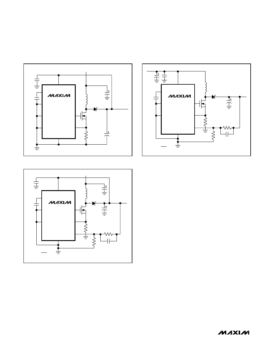
Figure 2a. 12V Preset Output, Bootstrapped
Figure 2b. 12V Output, Non-Bootstrapped
Figure 2c. 9V Output, Bootstrapped
MAX1771
V
IN
= 5V
REF
SHDN
AGND
GND
N
MTD20N03HDL
7
EXT
CS
FB
L1
22
µH
D1
1N5817-22
R1
18k
Ω
C4
300
µF
C5
100pF
C3
0.1
µF
5
4
6
1
8
3
2
V+
C1
68
µF
V
OUT
= 12V
AT 0.5A
R2
127k
Ω
R
SENSE
40m
Ω
C2
0.1
µF
V
OUT
V
REF
R2 = (R1)
(
-1
)
V
REF
= 1.5V
MAX1771
REF
SHDN
AGND
GND
N
7
EXT
CS
FB
C1
47
µF
L1
22
µH
D1
1N5817-22
R1
28k
Ω
C4
200
µF
C5
100pF
C3
0.1
µF
5
4
6
1
8
3
2
V+
V
OUT
= 9V
R2
140k
Ω
R
SENSE
40m
Ω
C2
0.1
µF
V
OUT
V
REF
R2 = (R1)
(
-1
)
V
REF
= 1.5V
Si9410DY/
MTD20N03HDL
V
IN
= 4V
MAX1771
V
IN
= 5V
REF
SHDN
FB
AGND
GND
N
7
EXT
CS
C2
0.1
µF
C1
68
µF
L1
22
µH
D1
1N5817-22
Si9410DY/
MTD20N03HDL
R
SENSE
40m
Ω
C4
300
µF
C3
0.1
µF
5
4
3
6
1
8
2
V+
V
OUT
= 12V
AT 0.5A