Max1771, 12v or adjustable, high-efficiency, low i, Step-up dc-dc controller – Rainbow Electronics MAX1771 User Manual
Page 14
MAX1771
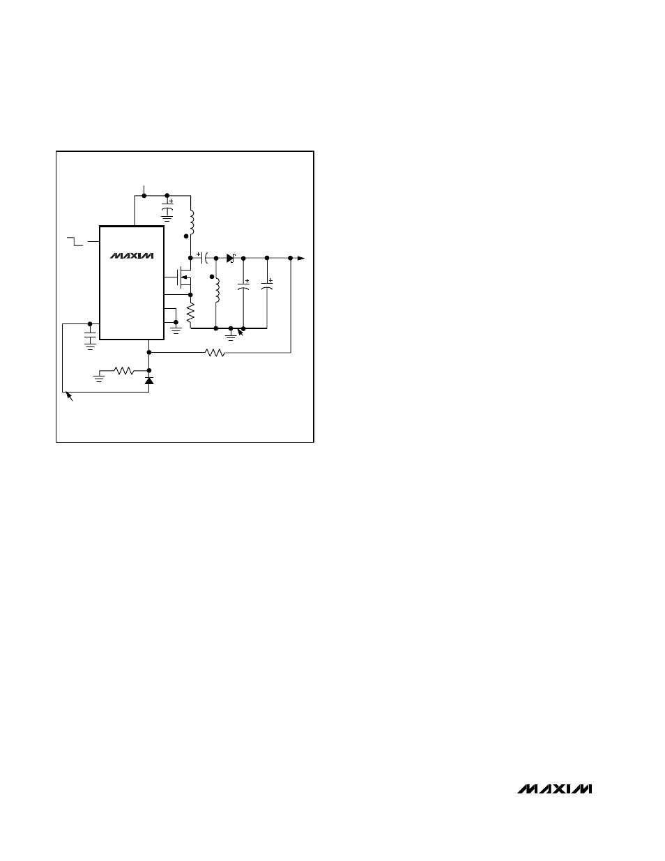
carefully observe the component voltage ratings, since
some components must withstand the sum of the input
and output voltage (27V in this case). The circuit oper-
ates as an AC-coupled boost converter, and does not
change operating modes when crossing from buck to
boost. There is no instability around a 12V input.
Efficiency ranges from 85% at medium loads to about
82% at full load. Also, when shutdown is activated
(SHDN high) the output goes to 0V and sources no cur-
rent. A 1µF ceramic capacitor is used for C2. A larger
capacitor value improves efficiency by about 1% to 3%.
D2 ensures start-up for this AC-coupled configuration
by overriding the MAX1771’s Dual-Mode feature, which
allows the use of preset internal or user-set external
feedback. When operating in Dual-Mode, the IC first
tries to use internal feedback and looks to V+ for its
feedback signal. However, since V+ may be greater
than the internally set feedback (12V for the MAX1771),
the IC may think the output is sufficiently high and not
start. D2 ensures start-up by pulling FB above ground
and forcing the external feedback mode. In a normal
(not AC-coupled) boost circuit, D2 isn’t needed, since
the output and FB rise as soon as input power is
applied.
Transformerless -48V to +5V at 300mA
The circuit in Figure 7 uses a transformerless design to
supply 5V at 300mA from a -30V to -75V input supply.
The MAX1771 is biased such that its ground connec-
tions are made to the -48V input. The IC’s supply volt-
age (at V+) is set to about 9.4V (with respect to -48V)
by a zener-biased emitter follower (Q2). An N-channel
FET (Q1) is driven in a boost configuration. Output reg-
ulation is achieved by a transistor (Q3), which level
shifts a feedback signal from the 5V output to the IC’s
FB input. Conversion efficiency is typically 82%.
When selecting components, be sure that D1, Q1, Q2,
Q3, and C6 are rated for the full input voltage plus a
reasonable safety margin. Also, if D1 is substituted, it
should be a fast-recovery type with a t
rr
less than 30ns.
R7, R9, C8, and D3 are optional and may be used to
soft start the circuit to prevent excessive current surges
at power-up.
Battery-Powered LCD Bias Supply
The circuit in Figure 8 boosts two cells (2V min) to 24V
for LCD bias or other positive output applications.
Output power is boosted from the battery input, while
V+ voltage for the MAX1771 is supplied by a 5V or 3.3V
logic supply.
5V, 1A Boost Converter
The circuit in Figure 9 boosts a 2.7V to 5.5V input to a
regulated 5V, 1A output for logic, RF power, or PCMCIA
applications. Efficiency vs. load current is shown in the
adjacent graph.
12V or Adjustable, High-Efficiency,
Low I
Q
, Step-Up DC-DC Controller
14
______________________________________________________________________________________
MAX1771
SHDN
R1
0.1
Ω
REF
AGND
R2
200k
Ω
1%
R3
28k
Ω
1%
GND
4
ON
OFF
5
FB
NOTE: HIGH-
CURRENT GND
Q1**
*SEE TEXT FOR FURTHER
COMPONENT INFORMATION
**Q1 = MOTOROLA MMFT3055ELT1
L1 + L2 = ONE COILTRONICS CTX20-4
3
6
EXT
CS
1
L1
20
µH
8
2
D1
1N5819
D2*
1N4148
C3
100
µF
16V
C1
33
µF
16V
C2*
1
µF
C5
0.1
µF
V+
V
IN
4.5V TO 15V
V
OUT
12V
250mA
L2*
20
µH
7
C4
100
µF
16V
NOTE: KEEP ALL TRACES CONNECTED
TO PIN 3 AS SHORT AS POSSIBLE
Figure 6. 12V Buck/Boost from a 4.5V to 15V Input