Max1771, 12v or adjustable, high-efficiency, low i, Step-up dc-dc controller – Rainbow Electronics MAX1771 User Manual
Page 10
MAX1771
approximately 2µs; select an inductor that allows the cur-
rent to ramp up to I
LIM
.
The standard operating circuits use a 22µH inductor.
If a different inductance value is desired, select L such
that:
V
IN
(max) x 2µs
L
≥ —————----—--
I
LIM
Larger inductance values tend to increase the start-up
time slightly, while smaller inductance values allow the
coil current to ramp up to higher levels before the
switch turns off, increasing the ripple at light loads.
Inductors with a ferrite core or equivalent are recom-
mended; powder iron cores are not recommended for
use with high switching frequencies. Make sure the
inductor’s saturation current rating (the current at which
the core begins to saturate and the inductance starts to
fall) exceeds the peak current rating set by R
SENSE
.
However, it is generally acceptable to bias the inductor
into saturation by approximately 20% (the point where
the inductance is 20% below the nominal value). For
highest efficiency, use a coil with low DC resistance,
preferably under 20m
Ω. To minimize radiated noise,
use a toroid, a pot core, or a shielded coil.
Table 1 lists inductor suppliers and specific recom-
mended inductors.
12V or Adjustable, High-Efficiency,
Low I
Q
, Step-Up DC-DC Controller
10
______________________________________________________________________________________
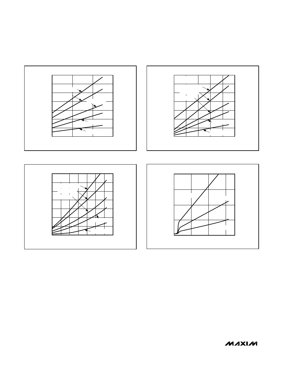
MAXIMUM OUTPUT CURRENT (A)
0
INPUT VOLTAGE (V)
0.5
1.0
1.5
2.0
2.5
3.0
3.5
2
3
4
5
R
SENSE
= 20m
Ω
R
SENSE
= 25m
Ω
R
SENSE
= 35m
Ω
R
SENSE
= 100m
Ω
R
SENSE
= 50m
Ω
V
OUT
= 5V
L = 22
µH
MAXIMUM OUTPUT CURRENT (A)
0
INPUT VOLTAGE (V)
0.5
1.0
1.5
2.0
2.5
3.0
3.5
2
4
6
8
10
12
R
SENSE
= 100m
Ω
R
SENSE
= 50m
Ω
R
SENSE
= 20m
Ω
R
SENSE
= 25m
Ω
R
SENSE
= 35m
Ω
V
OUT
= 12V
L = 22
µH
Figure 4a. Maximum Output Current vs. Input Voltage
(V
OUT
= 5V)
Figure 4b. Maximum Output Current vs. Input Voltage
(V
OUT
= 12V)
Figure 4c. Maximum Output Current vs. Input Voltage
(V
OUT
= 15V)
Figure 4d. Maximum Output Current vs. Input Voltage
(V
OUT
= 24V)
MAXIMUM OUTPUT CURRENT (A)
0
INPUT VOLTAGE (V)
0.5
1.0
1.5
2.0
2.5
3.0
3.5
2
4
6
8
10
12
14
16
R
SENSE
= 100m
Ω
R
SENSE
= 50m
Ω
V
OUT
= 15V
L = 22
µH
R
SENSE
= 20m
Ω
R
SENSE
= 25m
Ω
R
SENSE
= 35m
Ω
MAXIMUM OUTPUT CURRENT (A)
0
2
INPUT VOLTAGE (V)
0.8
6
10
14
0.2
0.4
0.6
V
OUT
= 24V
L =150
µH
R
SENSE
= 50m
Ω
R
SENSE
= 100m
Ω
R
SENSE
= 200m
Ω