Max3806 receiver for optical distance measurement, Detailed description, Applications information – Rainbow Electronics MAX3806 User Manual
Page 7: Pin description, Table 1. transimpedance gain settings
MAX3806
Receiver for Optical Distance Measurement
_______________________________________________________________________________________
7
Detailed Description
The MAX3806 preamplifier consists of a selectable-gain
transimpedance amplifier, a selectable 14dB attenuator,
and an output-driver block. The selectable-gain transim-
pedance amplifier linearly boosts the signal from the
photodiode. This block is followed by an attenuator
block that allows the user to attenuate the signal by
14dB selected by the ATT pin. The final block is the out-
put driver that can be disabled by asserting the DIS pin.
Transimpedance Amplifier
The selectable-gain transimpedance amplifier is con-
trolled by the GAIN pin. See Table 1 for gain settings.
Attenuator
The attenuator block can be set to pass the signal
through to the output stage with 0dB of attenuation
(ATT forced low) or with 14dB of attenuation (ATT
forced high).
Output Driver
The output driver is designed to drive an AC-coupled
load with an impedance of 2k
Ω or greater. The output
can be disabled by asserting the DIS pin high. When
the output is disabled, the OUT pin goes to a high-
impedance state. See Figure 1 for the equivalent output
circuit.
WARNING: The output is designed to be AC-coupled
to a high-impedance load. Operating the part with its
output DC-coupled to GND through a 2k
Ω or less load
may damage the output.
Applications Information
Settling Time
Settling time is the required time for the output to
achieve the final steady-state or AC amplitude swing
after a setting has been changed on the MAX3806. The
output common-mode voltage shifts when a change is
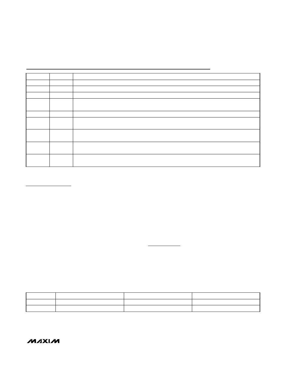
Pin Description
PIN
NAME
FUNCTION
1, 12
V
CC
5V
Power-Supply
Connection
2
IN
Amplifier Input. Accepts AC-coupled photodiode input current.
3, 4
GND
Supply Ground
5 ATT
CMOS/TTL Input. Assert this pin high to enable a 14dB attenuator in the amplifier. Force this pin low
to disable the attenuator. Contains internal 40k
pulldown resistor. Connect to GND if not used.
6, 8, 11
N.C.
Not Connected. This pin is not internally connected.
7 GAIN
CMOS/TTL Input. Selects amplifier gain setting. Force high for 60k
. Force low for 30k. Contains
internal 40k
pulldown resistor.
9 OUT
Amplifier Output. An increase in current into the IN pin causes the voltage at the OUT pin to decrease.
OUT must be AC-coupled to a load of 2k
or greater.
10 DIS
CMOS/TTL Input. Force high to disable the output of the MAX3806. Force low to enable the output.
Contains internal 60k
pullup resistor.
— EP
Exposed Pad. The exposed pad must be soldered to circuit board ground for proper thermal and
electrical performance.
Table 1. Transimpedance Gain Settings
GAIN
TRANSIMPEDANCE (k
)
LINEAR RANGE (μA
P
)
BANDWIDTH (MHz)
0 30
I
IN
40
98
1 60
I
IN
20
49