Output load – Rainbow Electronics DS1647P User Manual
Page 9
DS1647/DS1647P
9 of 11
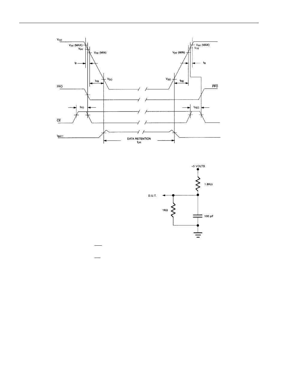
POWER-DOWN/POWER-UP TIMING
NOTES:
1. All voltages are referenced to ground.
2. Typical values are at 25
°C and nominal
supplies.
3. Outputs are open.
4. Data retention time is at 25
°C and is
calculated from the date code on the device
package. The date code XXYY is the year
followed by the week of the year in which
the device was manufactured. For example,
9225 would mean the 25
th
week of 1992.
OUTPUT LOAD
5. t
AH1
, t
DH1
are measured from
WE
going high.
6. t
AH2
, t
DH2
are measured from
CE
going high.
7. Real-Time Clock Modules (DIP) can be successfully processed through conventional wave-soldering
techniques as long as temperatures as long as temperature exposure to the lithium energy source
contained within does not exceed +85
°C. Post-solder cleaning with water washing techniques is
acceptable, provided that ultrasonic vibration is not used.
In addition, for the PowerCap version:
a. Dallas Semiconductor recommends that PowerCap Module bases experience one pass through
solder reflow oriented with the label side up (“live-bug”).
b. Hand soldering and touch-up: Do not touch or apply the soldering iron to leads for more than
3 seconds. To solder, apply flux to the pad, heat the lead frame pad and apply solder. To remove
the part, apply flux, heat the lead frame pad until the solder reflows and use a solder wick to
remove solder.