Ds1080l spread-spectrum crystal multiplier, Applications information, Typical operating circuit – Rainbow Electronics DS1080L User Manual
Page 7
DS1080L
Spread-Spectrum Crystal Multiplier
_____________________________________________________________________
7
Applications Information
Crystal Selection
The DS1080L requires a parallel resonating crystal
operating in the fundamental mode, with an ESR of less
than 90Ω. The crystal should be placed very close to
the device to minimize excessive loading due to para-
sitic capacitances.
Oscillator Input
When driving the DS1080L using an external oscillator
clock, consider the input (X1) to be high impedance.
Crystal Capacitor Selection
The load capacitors C
L1
and C
L2
are selected based
on the crystal specifications (from the data sheet of the
crystal used). The crystal parallel load capacitance is
calculated as follows:
For the DS1080L use C
L1
= C
L2
= C
LX
.
In this case, the equation then reduces to:
where C
L1
= C
L2
= C
LX.
Equation 2 is used to calculate the values of C
L1
and
C
L2
based on values on C
L
and C
IN
noted in the data
sheet electrical specifications.
Power-Supply Decoupling
To achieve best results, it is highly recommended that
a decoupling capacitor is used on the IC power-supply
pins. Typical values of decoupling capacitors are
0.001µF and 0.1µF. Use a high-quality, ceramic, sur-
face-mount capacitor, and mount it as close as possi-
ble to the V
CC
and GND pins of the IC to minimize lead
inductance.
Layout Considerations
As noted earlier, the crystal should be placed very
close to the device to minimize excessive loading due
to parasitic capacitances. Care should also be taken to
minimize loading on pins that could be floated as a pro-
gramming option (SMSEL and CMSEL). Coupling on
inputs due to clocks should be minimized.
C
C
C
L
LX
IN
Equation
=
+
2
2
C
C
x C
C
C
C
L
L
L
L
L
IN
Equation
=
+
1
2
1
2
1
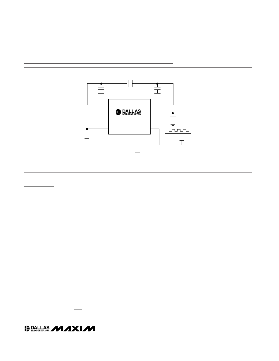
DS1080L
X2
NOTE: IN THE ABOVE CONFIGURATION WITH PDN CONNECTED TO V
CC
, SMSEL CONNECTED TO GND
AND CMSEL FLOATING, THE DEVICE IS IN NORMAL OPERATION WITH 2x CLOCK MULTIPLICATION, AND
SPREAD-SPECTRUM MAGNITUDE OF ±0.5%.
f
SSO
V
CC
V
CC
V
CC
SSO
PDN
X1
CRYSTAL
C
L1
C
L2
DECOUPLING
CAPACITOR
GND
CMSEL
SMSEL
8
7
6
5
1
2
3
4
Typical Operating Circuit