Ds1080l spread-spectrum crystal multiplier, Block diagram pin description – Rainbow Electronics DS1080L User Manual
Page 5
DS1080L
Spread-Spectrum Crystal Multiplier
_____________________________________________________________________
5
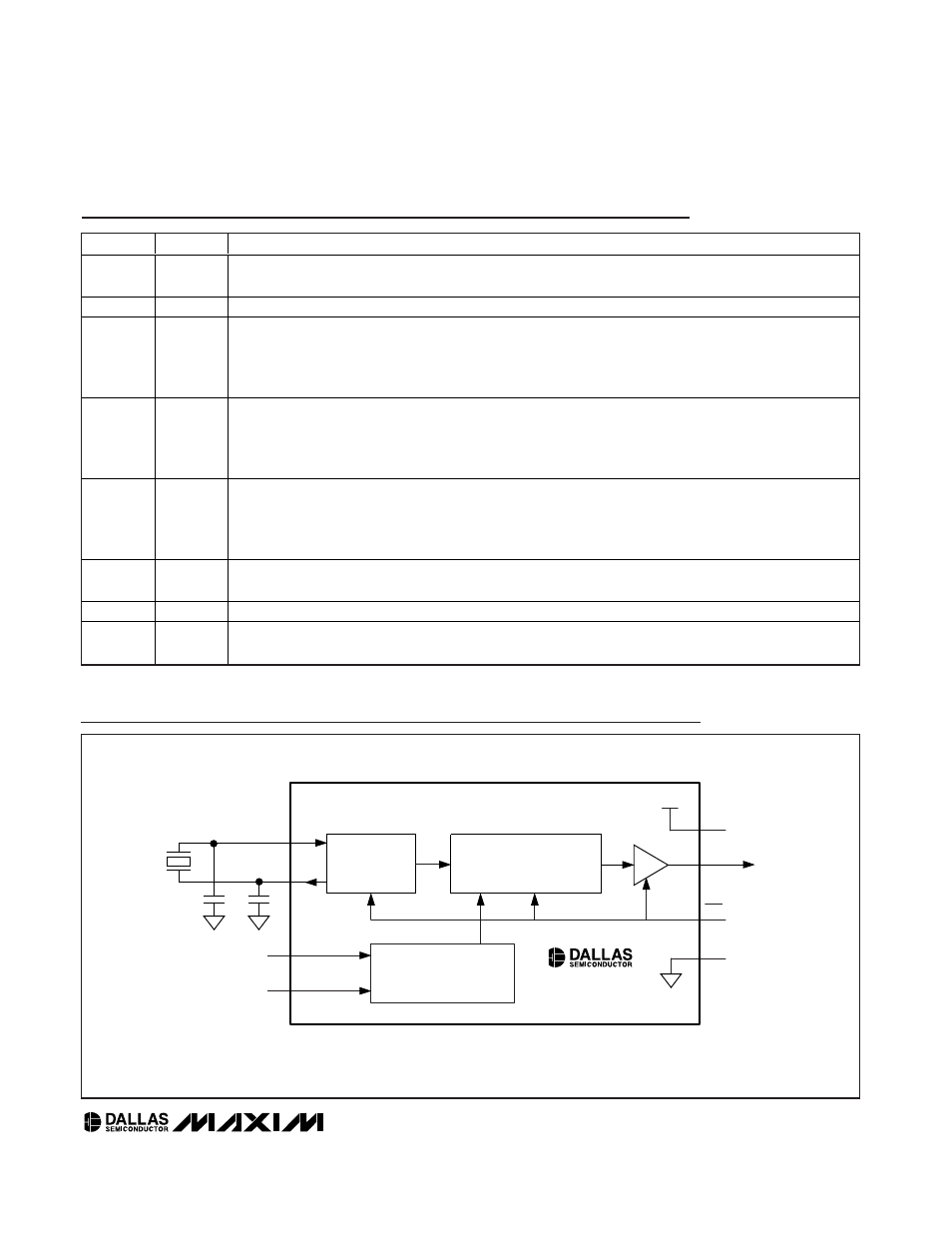
CRYSTAL
OSCILLATOR
1x/2x/4x CLOCK MULTIPLYING
PLL WITH SPREAD SPECTRUM
CONFIGURATION DECODE
AND CONTROL
V
CC
V
CC
GND
NOTE: SEE INFORMATION ABOUT C
L1
AND C
L2
IN THE APPLICATIONS INFORMATION SECTION AT THE END OF THE DATA SHEET.
PDN
SSO
CMSEL
SMSEL
X1
X2
16MHz
TO
33.4MHz
f
SSO
= 16MHz
TO
134MHz
C
L1
C
L2
f
IN
f
SSO
DS1080L
Block Diagram
Pin Description
PIN
NAME
FUNCTION
1
X1
Crystal Drive/Clock Input. A crystal with the proper loading capacitors is connected across X1 and X2.
Instead of a crystal, a clock can be applied at the X1 input.
2
GND
Signal Ground
3
CMSEL
Clock Multiplier Select. Tri-level digital input.
0 = 1x
Float = 2x
1 = 4x
4
SMSEL
Spread-Spectrum Magnitude Select. Tri-level digital input.
0 = ±0.5%
Float = ±1.0%
1 = ±1.5%
5
PDN
Power-Down/Spread-Spectrum Disable. Tri-level digital input.
0 = Power-Down/SSO Tri-Stated
Float = Power-Up/Spread Spectrum Disabled
1 = Power-Up/Spread Spectrum Enabled
6
SSO
Spread-Spectrum Clock Multiplier Output. Outputs a 1x, 2x, or 4x spread-spectrum version of the crystal
or clock applied at the X1/X2 pins.
7
V
CC
Supply Voltage
8
X2
Crystal Drive Output. A crystal with the proper loading capacitors is connected across X1 and X2.
If a clock is connected to X1, then X2 should be left open circuit.